

1⁄16Trumpeter M16 Halftrack
5
Comments
Introduction
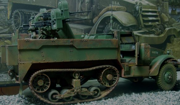
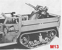
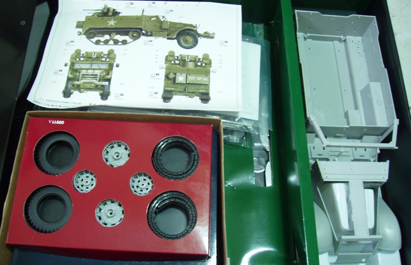
The US M13 was an M3 Half-track with hinged rear flaps that folded down, and an electrically powered Maxson twin .50caliber gun turret on the rear bed. The M16 was the M13, but with a quad .50cal Maxson mount. The M16 was the standard anti-air vehicle for the US Army to the end of WW2. During the 1950s, Monogram released a 1/35 M13 kit with dual .50 calibre guns. In the 1970s, Tamiya released its classic 1/35 M16. Dragon did not release its superb M16 kit until September 2008. I have been excitedly anticipating the arrival of Trumpeters 1/16th M16 as much as anyone has, especially after building all of Trumpeters 1/16th scale T-34 series. I ordered this kit and booked time off work. Ah some people holiday at the beach not me. To say this kit is big is an understatement. No need to cover the same ground as Toadman in his overview of the over 726 parts contained in the box. Suffice to say this kit is a massive project. See Chris Hughes' excellent review here: Trumpeter's M16: In-Box Review by Toadman (LINK)Construction
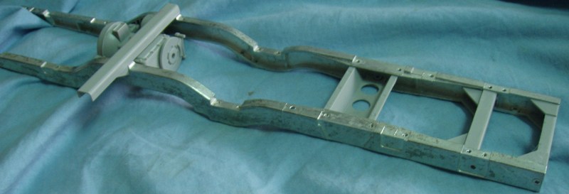
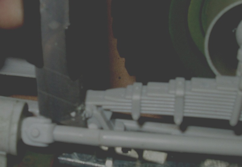
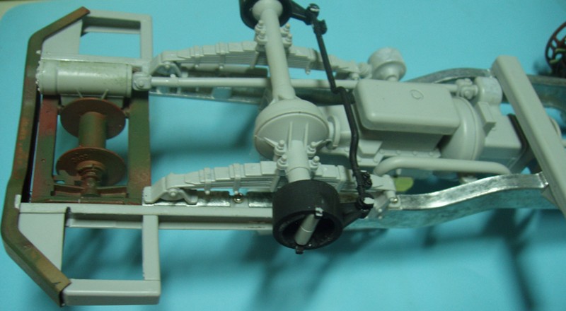
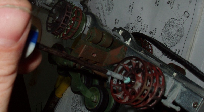
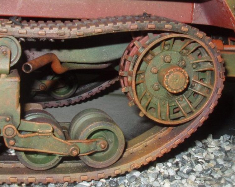
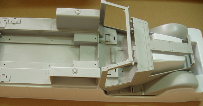
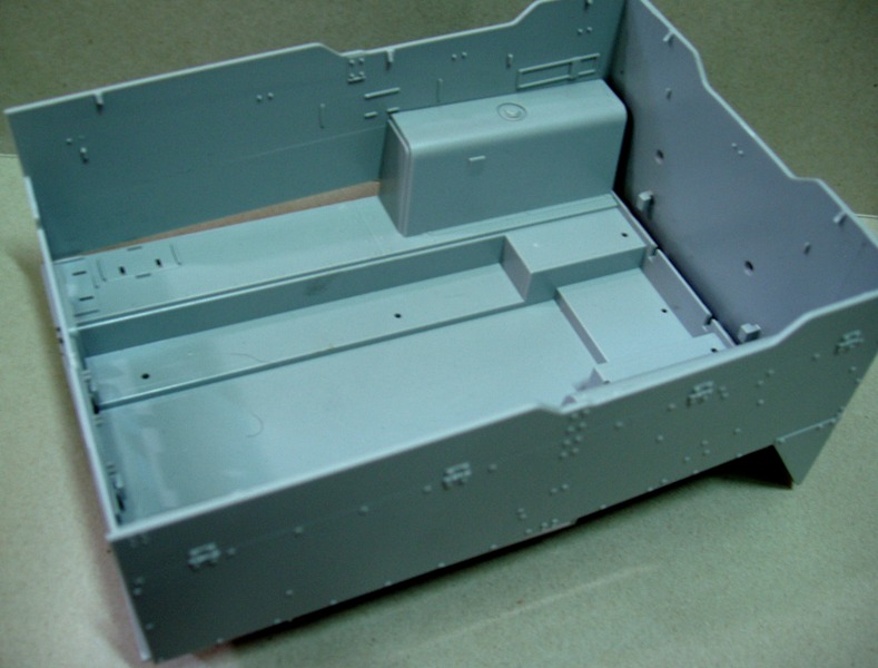
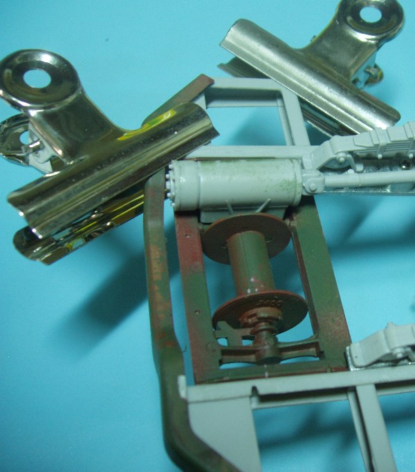
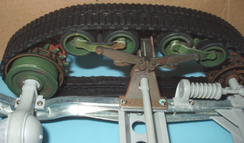
Chassis Chassis Construction begins with setting the gearbox and cross members between those sturdy metal chassis members or, frame rails. Confusingly, part Z28 is installed during step #6, but is shown as already installed in Step #1. Caution: do not cement anything at this stage; loosely locate the parts using the screws provided. I use a bit of gummy Blue Tac on the head of the screw to start it in the threads (See photo, Below) Its important to get the front of the frame rails parallel and the correct distance apart, or youll have grief later when installing the winch in Step 7. Take a break and construct the winch and exhaust assembly, the later being held to the frame rail with a long screw. Very clever, very easy. Dont be a perfectionist about the seam youre left with after assembling the axles (parts B5/B6). Remember, those axle cases were cast as a single unit, and have a rough seam. Screw the axles and leaf springs on: again, dont commit to the super glue yet! The front wheel will swivel by use of rubber cups between the axle ends and steering knuckles (See photo, Below). A word to the wise: that very long drive shaft (parts Z46 and Z45) must make a perfectly straight line between the transfer case and the winch. A15 and A18 are inner tubes for the front tires, but are entirely unnecessary omitting them will make insertion of the front wheel rims (parts U13 and U 14) much easier: I clamped the rims together inside the tire using a C-clamp from my desk lamp while the super glue dried. After engine installation, the PE stone guards (PE 20 and 21) may be installed. The appropriate bends to make are vague in the instructions so youll have to guess-timate the angles. Step 11 concerns construction of that robust front bumper. Use a pair of spring clamps to get all the brackets square and at right angles to each other (See photo, Right). A slip-up here will be very noticeable! Start on construction of the bogies. The suspension is not intended to be "workable". Enlarge the two holes in part A1, and insert the springs (parts U1) as your first step. Sixteen rubber tires are provided for the eight road wheels. Each tire has a groove that should face inward. Do not over-tighten those screws! Again, locate all the finished sub-assemblies onto the chassis using screws, not glue. Note that the tube (part # A12 ), connecting the bogies, is too long: I sanded about 2 mm off each end (Fig. 5). Two are provided in the kit, so dont be too nervous. Once everything is installed to the chassis, the major sub-assemblies can be cemented with super glue. This will ensure strength. The outside face of the sprocket drive wheels are cursed with injector pin marks unfortunately placed between each strengthening rib. A smear of putty for each will make this hardly noticeable, once some heavy weathering is applied. Install the sprockets and idler wheels, the drive sprockets I affixed by super-gluing part A16 to the axle case. This will provide some strength, as the tension in those rubber tracks will put great strain on the whole assembly. Tracks Flatten the lengths of track as you gently warm them with a hair dryer. Although no clue is given in the instructions, yes, theyre archaic rubber band affairs employing the age-old connection method of pins you mash-down with a heated screwdriver (See photo, Below). But surely not? Is this really the year 2008? Since the tracks on the real vehicle were metal with rubber endless belt casings vulcanised onto them, these tracks will actually look okay. The inside of the tracks have no detail, however. Mine had nasty flash on most edges where they seem to have been carelessly torn from their sprues. Id much rather have had them come still attached to the sprue, rather than neatly rolled inside a box! Though there is really no sag in these tracks as in conventional link type caterpillar tracks, I used wire to snug the track to the idlers and sprockets (see photo below). With the tracks connected, fit them around the sprocket, road wheels, and halfway around the rear idler wheel. Gently rotate the idler and ease the tracks around. Worry not; the whole suspension assembly is sturdier than it appears. Now you can see why it is static, rather than working.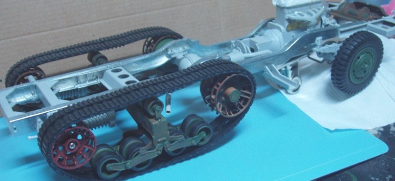


About the Author


FROM: TAIPEI, TAIWAN / 台灣
From B.C., Canada. Living in Taiwan for past several years. I've been building kits for as long as memory serves -armor, aircraft, cars. Big fan of 1/16th scale armor kits. Currently serving as poster boy for working with CA adhesives in a well-ventilated area. My first kit was the positively awful ...
Comments

Thank you Ted,for the write up. I too made those fixes you described.
I made my own gun solenoids,and used images from Hunnicutt's halftrack book,to lead the wires into the mount.
My track is a bit tighter around the running gear,I hid the "joint" in the sprocket area. Also,I used fine fishing line to tie down the track to the sprocket and idler,this helped the overall view.
I noticed there was a top radiator hose,but no lower.The connection point on the engine is there,so I made one from a piece of wire which had black insulation on it. Also I had to fabricate an adjustment bar for the generator,as there was none on the engine.
I suppose for the missing ammo belts,a series of round sections of styrene rod,or stretched sprue glued side by side would be good to use as a substitute.
JUN 11, 2009 - 11:36 AM

Very awesome build and write-up! I couldn't read the whole article tonight, but what I saw I did like and saved it to my favorites. I also am into 1/16th kits and have been eyeing this one for awhile and can't decide on it or waiting for the R/C version, which is slated to be released later this year.
Lots of tips so thanks for sharing it with us!
JUN 11, 2009 - 01:18 PM

Not to detract from the amazing work done on this huge model, but the 50th Artillery Battalion (Automatic Weapons, Self Propelled) did exist. There are a number of references to this unit in Korea. It would have been equipped with the M16 during that time frame as well.
Also the M55 designation applied only to the M45C mount + the M20 trailer.
Regardless, this is a truly impressive piece and thanks for sharing.
JUN 12, 2009 - 04:12 AM
Thank you!!!!
I've been looking for one of these blogs, good job Ted.
We still have the track problem, anybody find a good way around this?
Dan
JUN 12, 2009 - 11:43 AM

I'm very surprised that the AM folks haven't jumped to produce extras for this kit. It's many flaws aside, it still has no rivals in this scale. I was shocked. however, to see how much it's selling for in your part of the world. For my money, I'd rather save-up and get the 1/16th King Tiger instead -far better value-for-money!
JUN 12, 2009 - 03:32 PM
Copyright ©2021 by Ted Hayward. Images and/or videos also by copyright holder unless otherwise noted. The views and opinions expressed herein are solely the views and opinions of the authors and/or contributors to this Web site and do not necessarily represent the views and/or opinions of Armorama, KitMaker Network, or Silver Star Enterrpises. All rights reserved. Originally published on: 2009-06-11 00:00:00. Unique Reads: 27076

WEB HOSTING BY


Copyright ©2021 Armorama and Kitmaker Network, a subsidiary of Silver Star Enterprises
All Rights Reserved. Please read our Conditions of Use and Privacy Policy.
All Rights Reserved. Please read our Conditions of Use and Privacy Policy.