

1⁄35Building DML's Sdkfz 234/3
3
Comments
Introduction
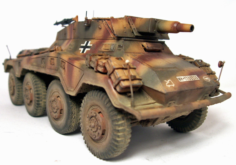
The SdKfz 234 series was designed as a replacement to the earlier SdKfz 231/232 eight-wheeled armored cars and there were four versions built, with the 234/3 armed with a 7.5cm KwK51 L/24 and a 7.92mm machine gun in an open-top superstructure. These vehicles were produced starting in June 1944 and were gradually phased out toward the end of 1944 in favor of the 234/4 armed with the 7.5cm PaK 40 L/46. The vehicle carried 50-55 rounds of ammunition and weighed 9.8 tons.The Sdkfz 234/3 Schwerer Panzerspahwagon (7.5cm) is the fourth version in the 234 series to be released by Dragon.suspension and lower hull
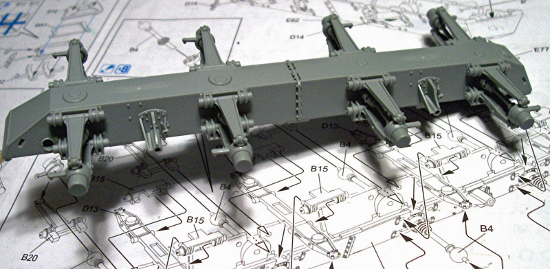
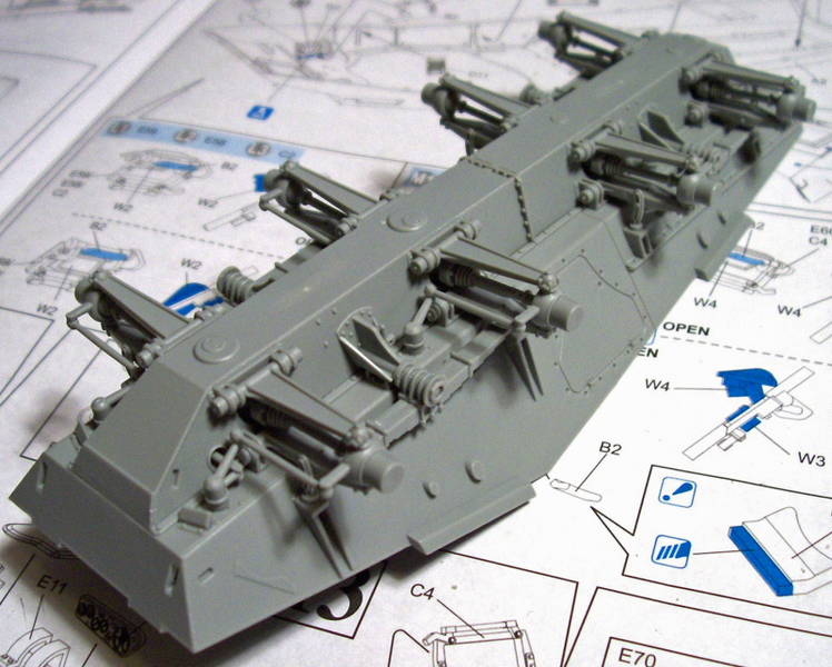
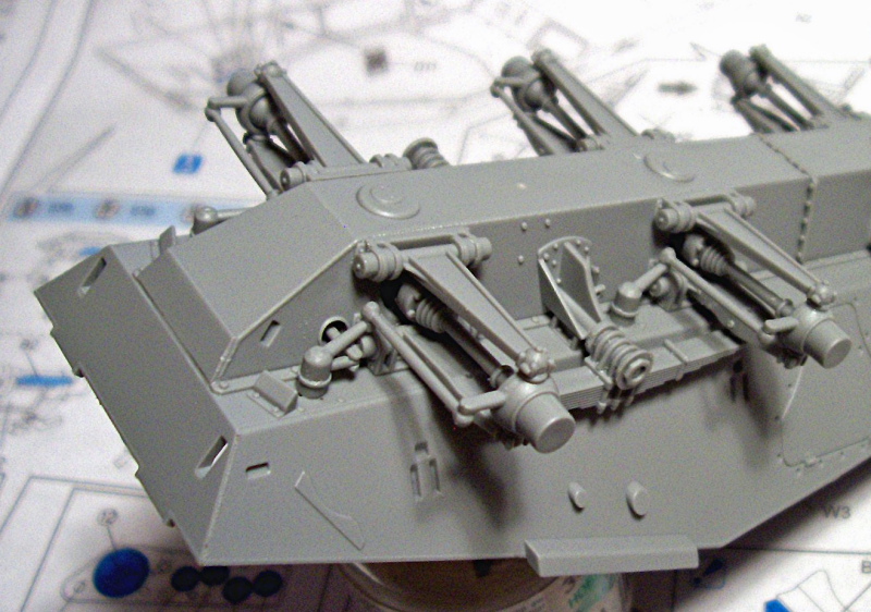
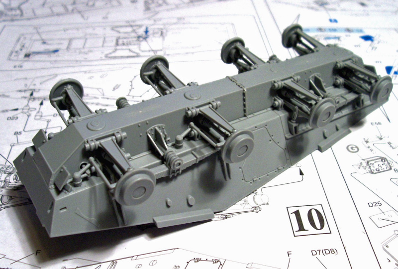
The build began as usual on the lower hull and running gear with steps 1 and 2 focusing mainly on the axles, ball joins and their supports. At first glance, this looks quite complicated but after studying the instructions for a few minutes and taking it slowly it really wasn't too bad at all. The only small problem I had was the ball joints themselves being a tight fit, but a little sanding took care of that and everything else fell into place. The most important thing to watch for was making sure everything was in alignment. Continuing on, I attached the leaf springs which rounded out step 3. I deviated from the instructions which would have you working on the lower hull interior and instead jumped to steps 8, 9 and 10 which finished out the remainder of the drive assembly right up until attaching the wheels. The instructions might look a tad confusing here but are in fact very straight forward and I didn't have any fit problems at all.interior
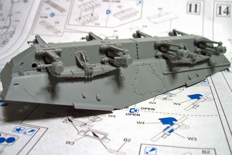
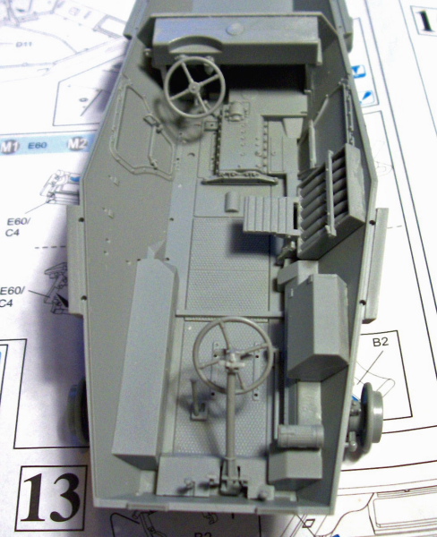
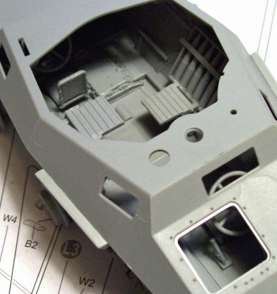
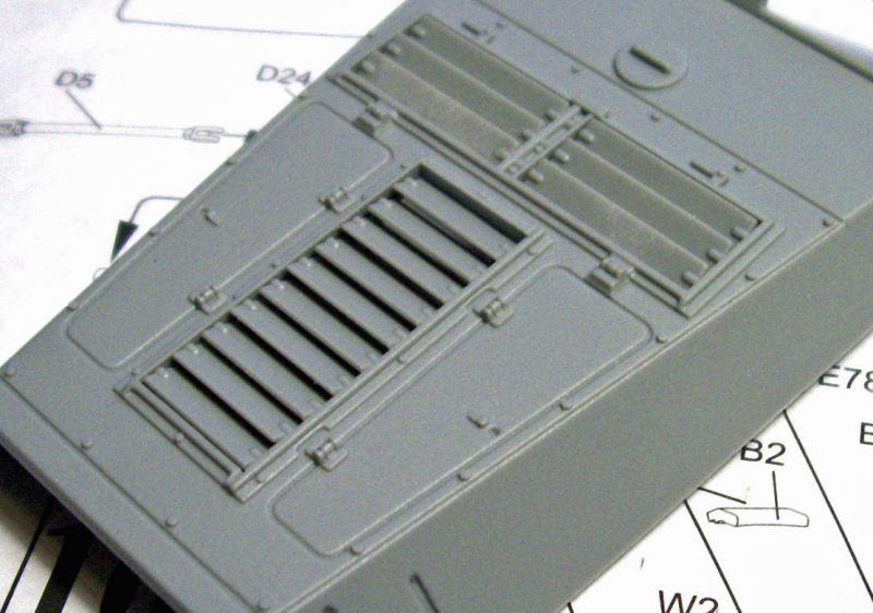
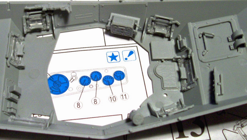
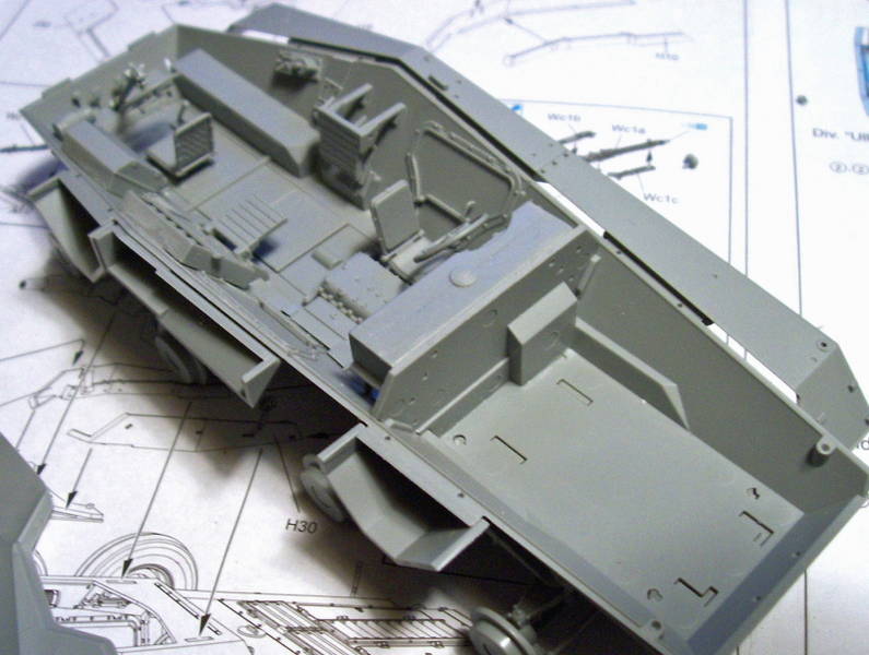
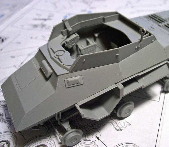
With the drive assembly finished, I decided to jump back to steps 4, 5, 6 and 7 and begin the interior. Step 4 focuses mainly on the rearward driving station, the transmission cover, and a large floor plate. The wall that divides the drivers' compartment from the engine compartment (part E30) was a bit of a tight fit. Once it was in I did a test-fit of the upper hull and found it was holding the upper section off just a little so i sanded the top of the plate down a bit until the upper hull was a snug fit once more. Step 5 consisted of 8 small sub-assemblies which are to be added during steps 6 and 7. There are 2 seats, one ammo box with attached seat, a radio, a set of pedals and a steering column and finally a storage box. The only thing to note here is during step 5 on sub-assembly "E" the ammo box with attached seat the brackets (parts H4 and H5) are backward and should be switched around. Other than that, I had no problems here or with steps 6 and 7 and everything fit inside perfectly and looks very nice and busy although I don't think too much of it will be visible in the end. Once the lower interior was finished, I moved straight onto the upper interior with steps 11, 12 and 13. There is quite a lot of detail involved here, for example all the vision slits are workable if so desired. I found them to be a bit fiddly and had no reason to want them workable, so I fixed all mine closed as i went except the drivers' slit. I left this open but it is glued and not workable. It is also at this point the vents on the engine deck are fitted and there is a choice of open vents or closed. I chose to go with the open ones simply for looks. Also during step 11, you are instructed to remove a cap and two bolts from the left side rear hull and then drill two holes which are for adding an extra antenna using parts C8, C11 and C12. However, nowhere in the instructions does it tell you this so if you do not want to add the antenna don't remove the bolts/cap or drill out the holes. I began step 14 but only mounted the inner forms for the fender boxes and the rear plate. The rest of this step calls for you to join the upper and lower hulls and mount the fenders. Since the interior needed painting before that was done, I once again jumped forward in the instructions to step 27 which is the armor plates for the gun position and the gun's mounting plate. All the parts are on the H sprue and there are a couple of mistakes in the instructions, each side armor plate consists of two parts and we are told H29 mates to H10 and H30 mates to H12 but this is in fact opposite and easy to spot. Also, the gun mount calls for a bolt (H32) and the MG mount on the rear plate (H2) but these should also be switched.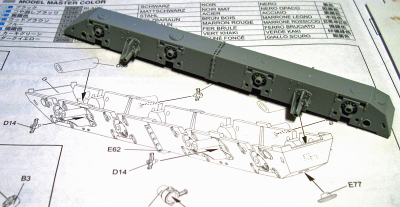


About the Author


FROM: TENNESSEE, UNITED STATES
My name is Ron and i began modeling in january of 2005 while off work with knee surgery i have always been interested in the military and 1/35 scale vehicles and armour are my main subjects, i will build just about any brand of kit there is as long as it interests me and i build for my own collectio...
Comments


Hi Ron
Great modelling as always.
I admire not only the sheer quantity of models you seem to be able to make (whilst I'm still messing about with one figure), but also the consistent high quality.
Also the fact you seem to be able to create a feeling you are looking at a ton of metal not a little plastic kit.
I'd really like to see you put some of these into a matching diorama, I think it would look very realistic.
All the best
Alan
OCT 01, 2007 - 11:10 PM

Copyright ©2021 by Ron Goins. Images and/or videos also by copyright holder unless otherwise noted. The views and opinions expressed herein are solely the views and opinions of the authors and/or contributors to this Web site and do not necessarily represent the views and/or opinions of Armorama, KitMaker Network, or Silver Star Enterrpises. All rights reserved. Originally published on: 2007-10-01 00:00:00. Unique Reads: 23959

WEB HOSTING BY


Copyright ©2021 Armorama and Kitmaker Network, a subsidiary of Silver Star Enterprises
All Rights Reserved. Please read our Conditions of Use and Privacy Policy.
All Rights Reserved. Please read our Conditions of Use and Privacy Policy.