History
The United States entered WWII with the M3 light tank series, which, with their thin, vertical armor and 37mm gun, were considered obsolete. The design was slightly improved with the M5 series, which added sloped armor, but retained the 37mm gun. As a result, in 1943, the Ordinance Board requested a new light tank design. To speed delivery, it was to use the drive train of the M5 series. The new tank, designated light tank M24, weighed in at 20 tons, had a much improved, lightweight 75mm gun that was initially designed for the B-25H medium bomber, torsion bar suspension and wider tracks, a larger, 3 man turret, and vastly improved speed and mobility. The M24 could reach speeds of 35mph (56kp/h) on roads, 25mph (40kp/h) off road. The armor was only 25mm thick, but was sloped at 60 degrees. The first units reached the front lines in Italy and NW Europe in November 1944 and crews liked them from the start. The thin armor made them vulnerable to nearly all German armor, but their speed and mobility were a tremendous advantage, and the new gun at least gave them a fighting chance. A total of 4,731 vehicles were built by the end of WWII, with a variety of self propelled gun platforms being built on the chassis.
introduction
I had always planned on getting a kit of the M24, but my interest grew after speaking with a former tanker at a Veteran's Day performance at my son's school. He had served from 1946-48, and was carrying a 1/32 scale toy of the M24 in his hands. He told me that the interior of the M24 was still cramped, but much bigger than the M5A1 he had trained on. What he remembered most was how fast it went, and how much the crew enjoyed getting the tank up to speed. As he spoke, the M24 moved up my priority list of kits to build. I looked at the Italeri kit but many modelers recommended I wait as
Bronco had announced they would be offering one in the near future. I watched the online hobby shops and ordered the kit the day I saw it available.
contents
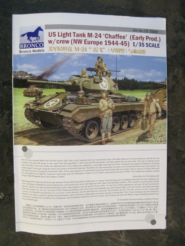
The kit comes in a large, top opening box featuring artwork of a tank from the 1st armored division in Italy, crew members, based on the included Dragon US tank crew NW Europe 44-45, in and around the tank. They are dressed for cold weather, but the background appears green and sunny. Inside the box are 745 parts in tan styrene, 16 clear parts, a photoetch fret and a piece of string. Decals for 3 vehicle markings are included, and a second decal set of 1st division markings for the crew figures is included. The instructions are in booklet form, 26 pages long. Specifics on the kit contents are as follows:
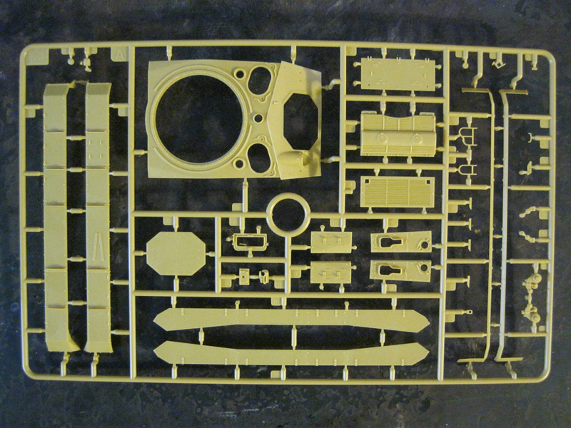
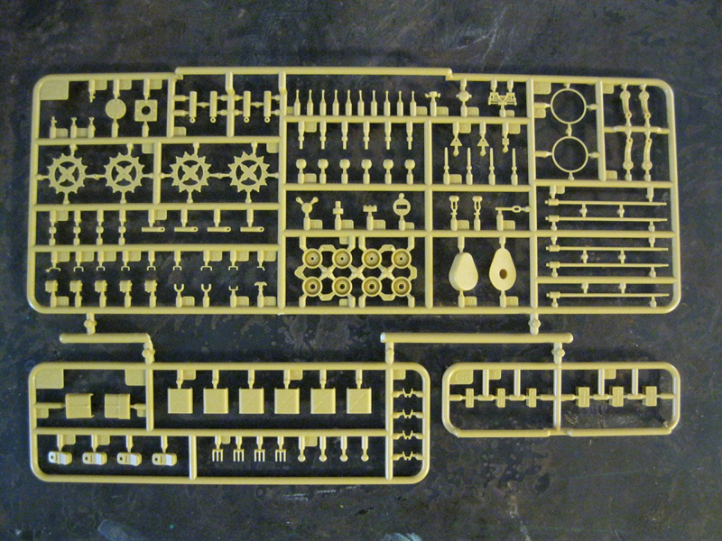
"A" sprue, upper hull section, rear deck sections, track guards, sand shields and brackets.
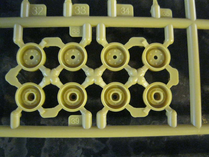
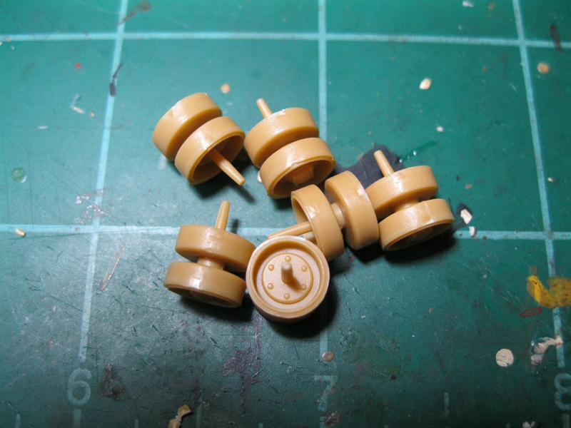
"Ca", x5 sprue, road wheels, with separate inner wheel and outer rim and tire sections.
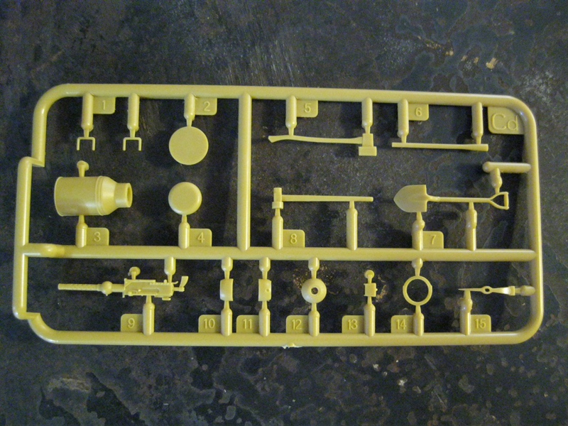
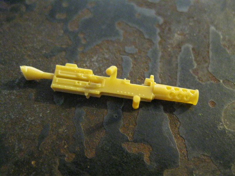
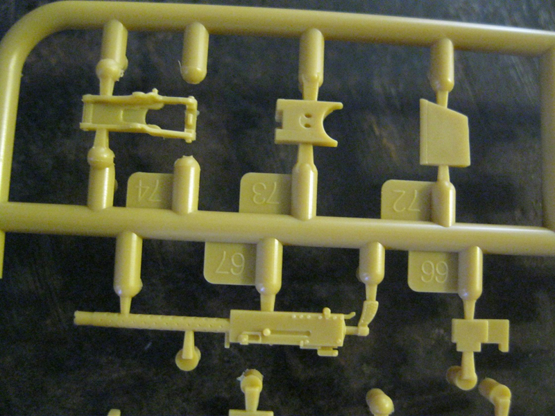
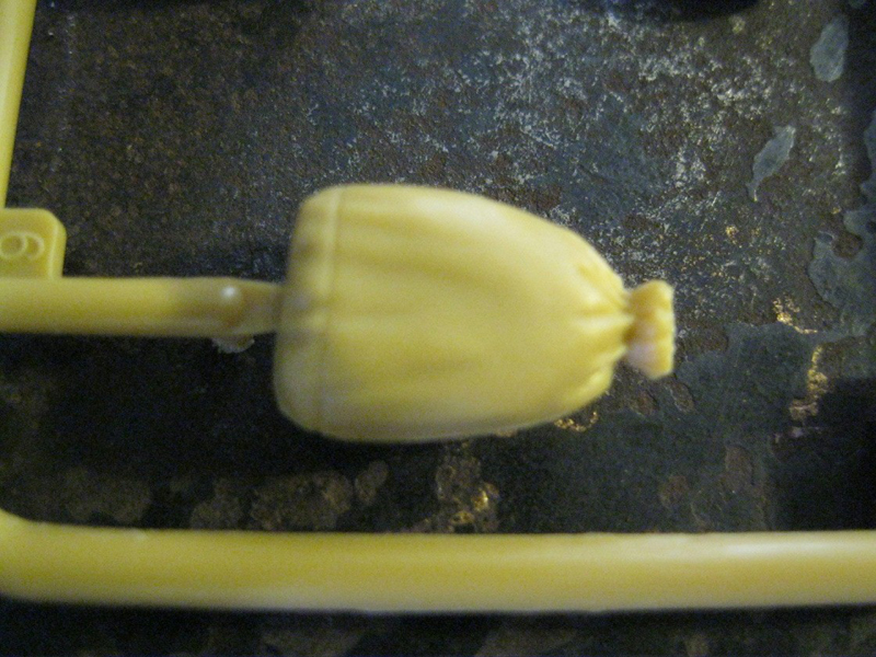
"Cd" sprue, with tools, bow MG and milk jug.
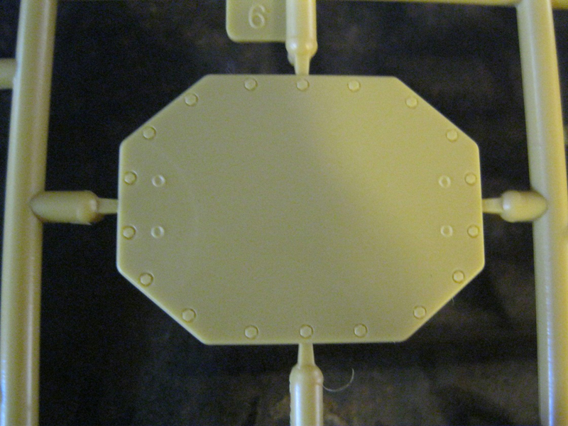
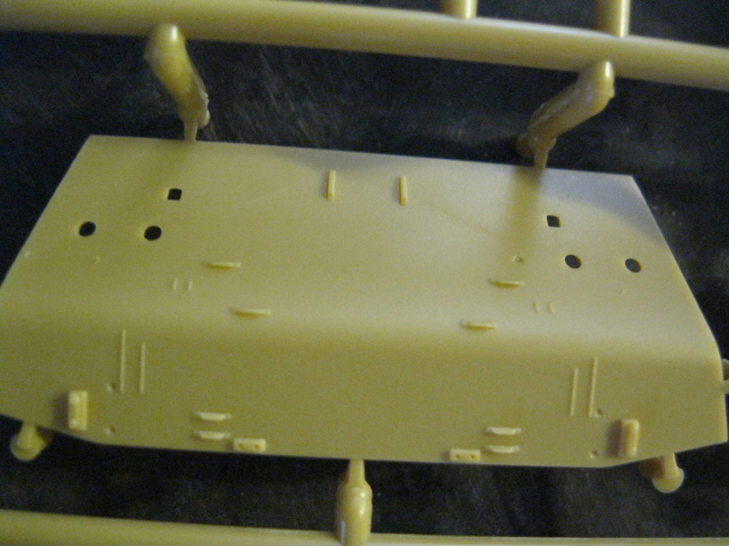
"Da" sprue, front and rear hull plates.
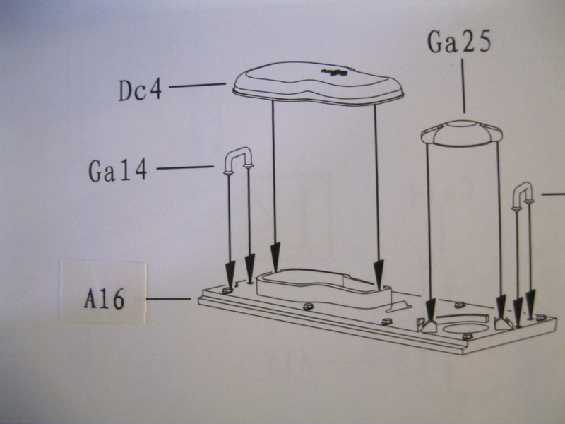
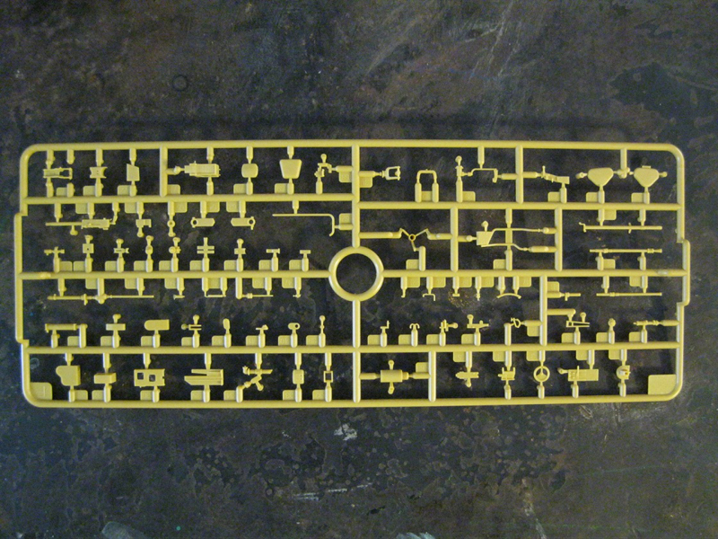
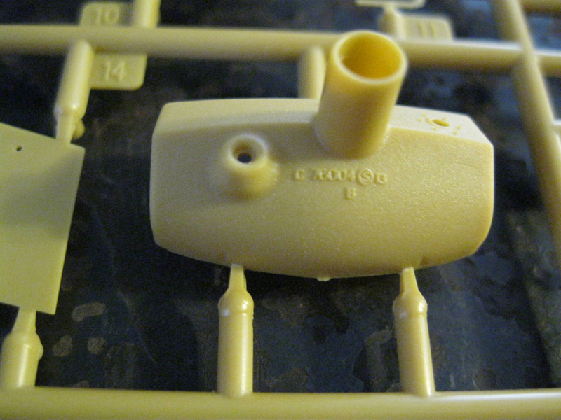
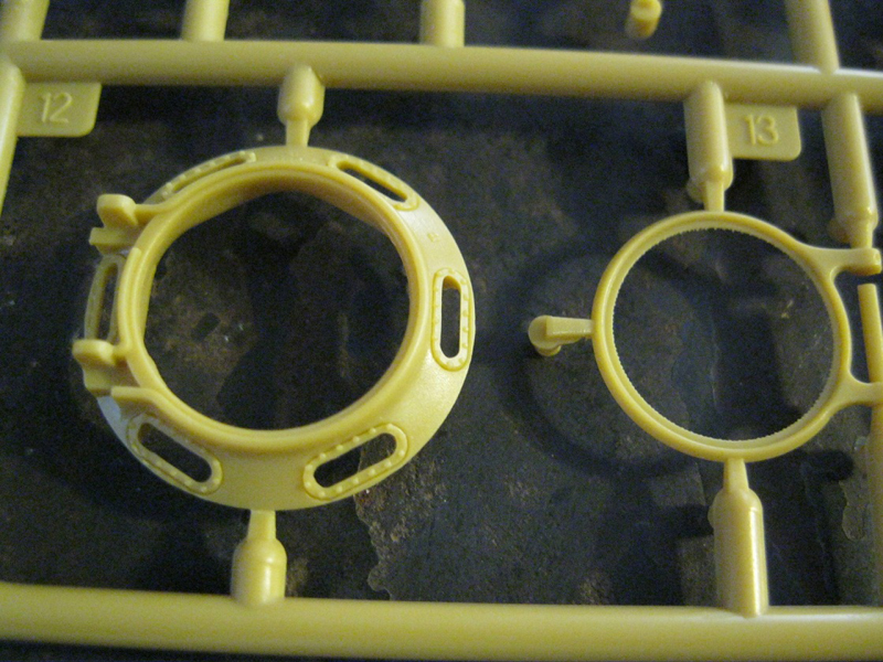
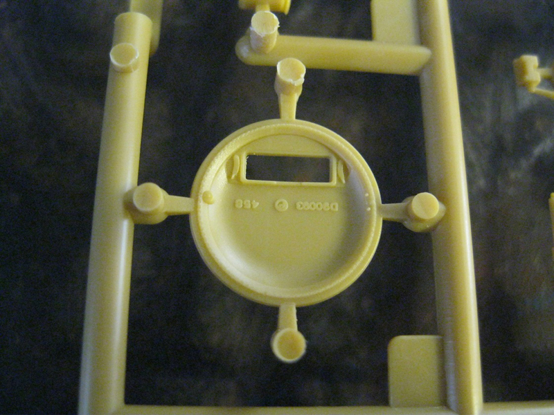
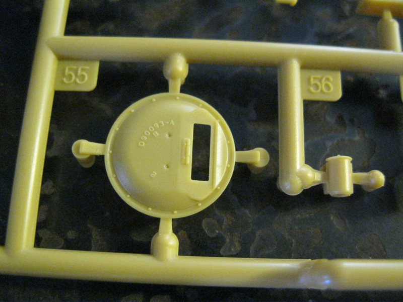
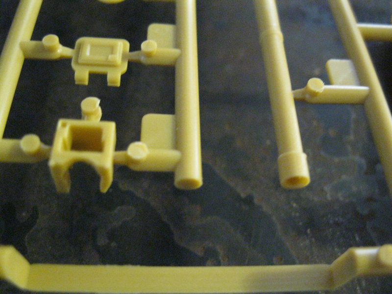
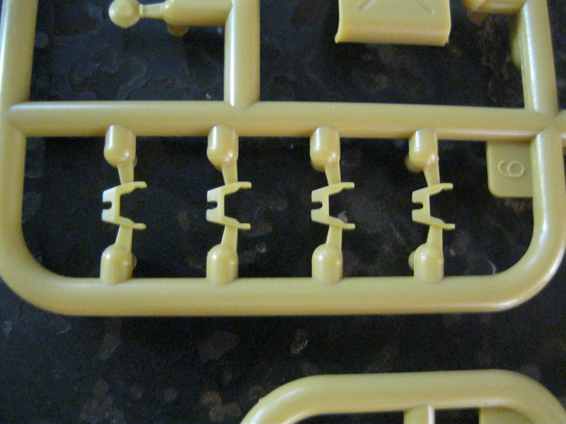
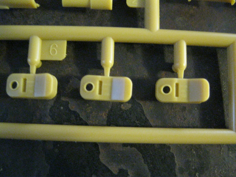
"Dc" sprue, torsion bar covers, suspension parts and cast hatch covers and fuel system vent covers.
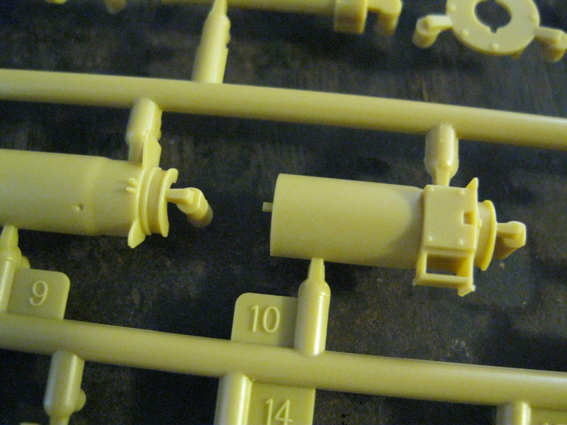
"E" sprue, turret and detail parts, main gun.
"F" sprue, gun breech and inner turret parts.
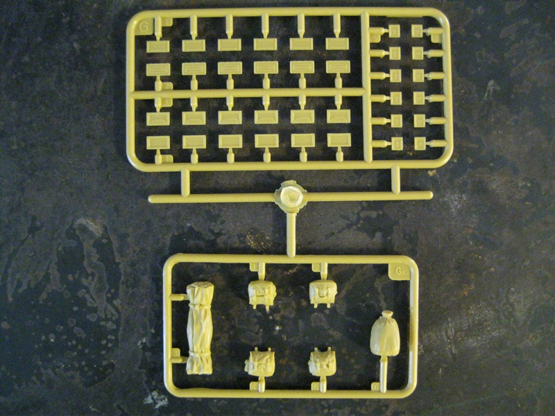
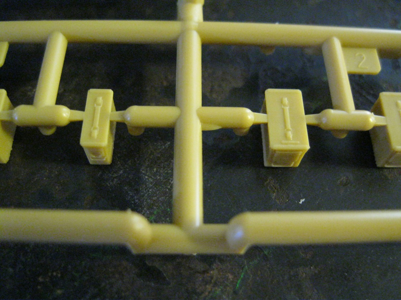
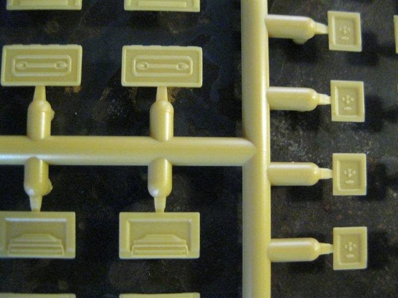
"G" sprue, .50 cal ammo boxes.
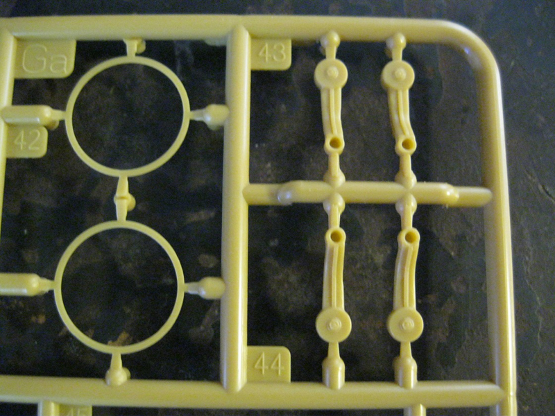
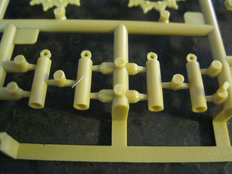
"Ga" x2 sprue, torsion bars, suspension parts, return rollers and drive sprocket parts.
"Gb" sprue, 5 gal. jerry cans.
"I" and "K" parts, inner hubs for drive sprockets and idler wheels.
"L" sprue, clear parts.
"M" sprue, lower hull tub.
"N" sprue, x14, 12 indy link tracks per section.
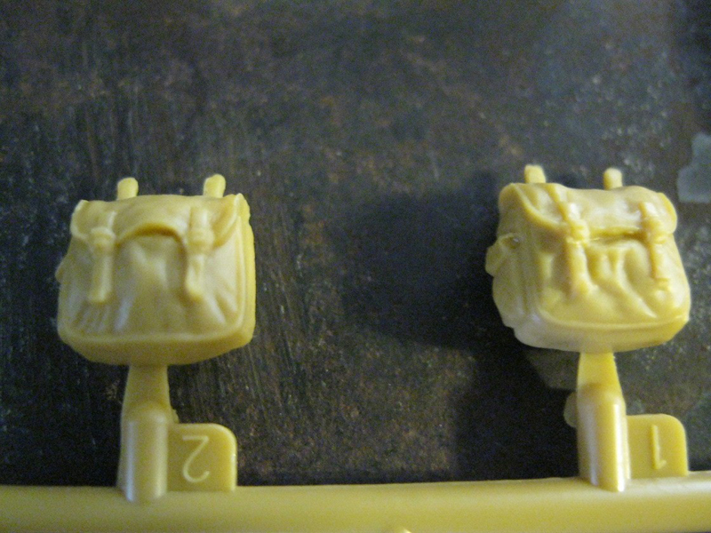
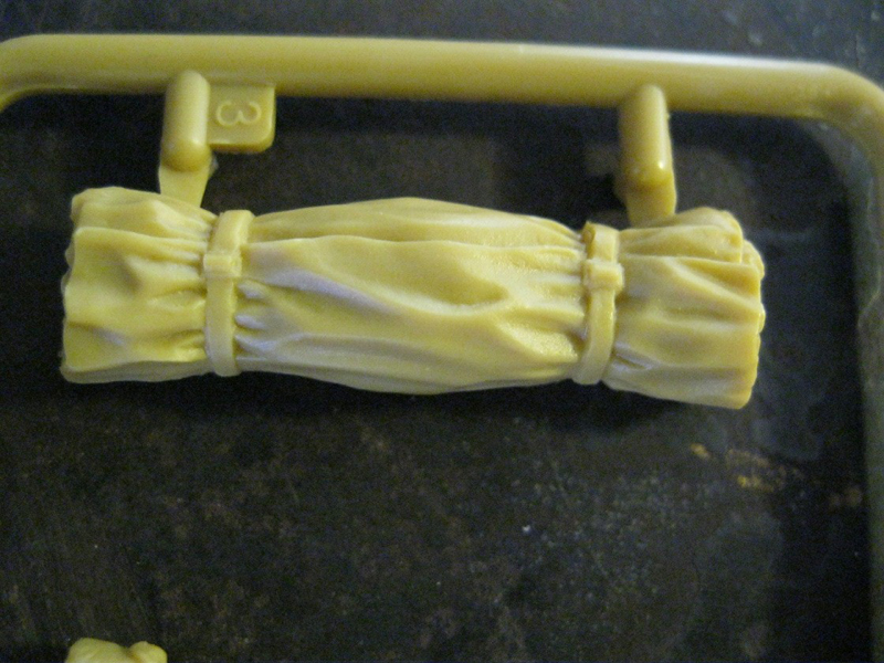
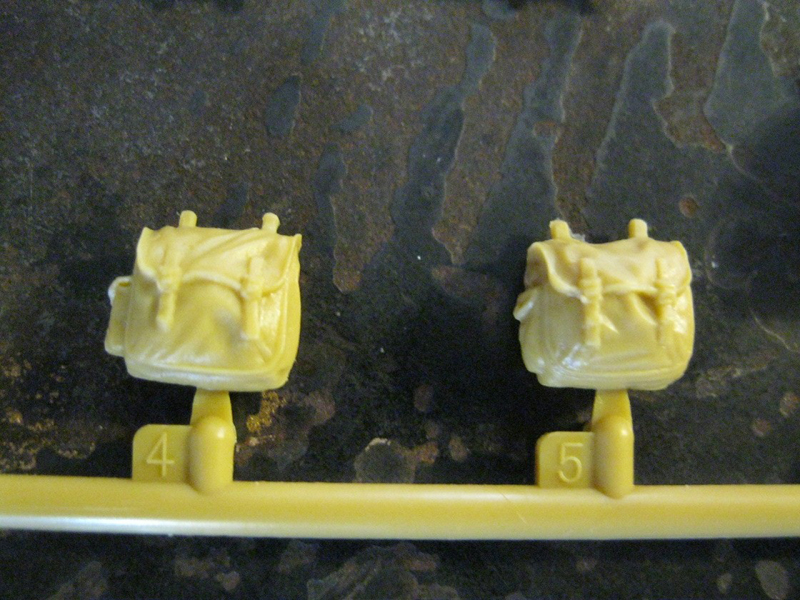
"T" is four haversacks, one duffel and one rolled tarp.
"W", receiver for .50 cal MG.
"X" recoil spring for main gun.
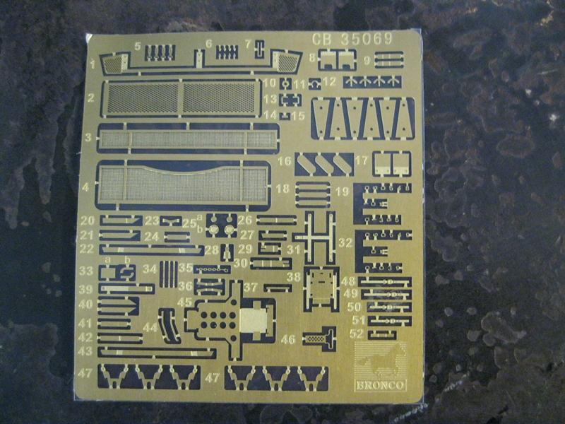
"P" is a photo etch fret.
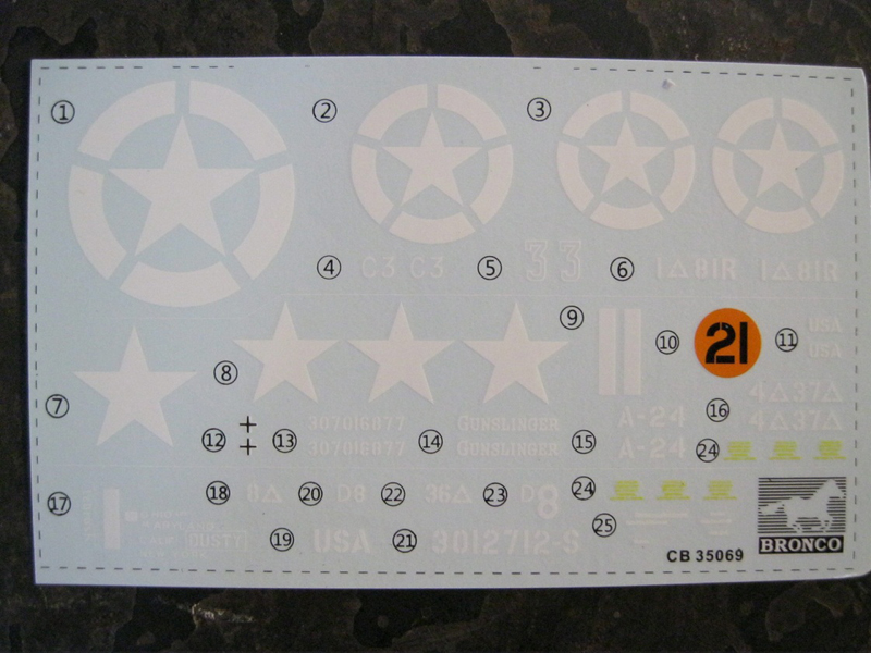
One decal sheet with markings for 3 vehicles.
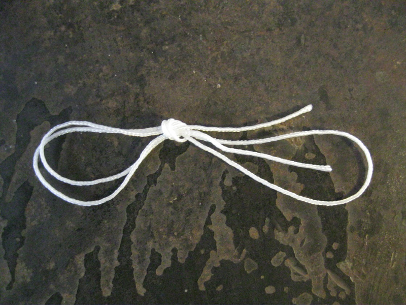
One piece of string for the tow cable.
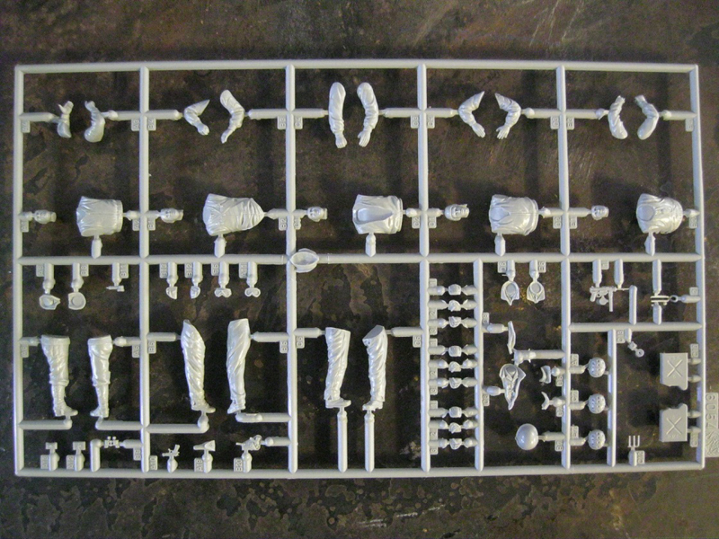
"Q" sprue, gray styrene. These are the figures from Dragon. 3 full figures and 2 half figures.
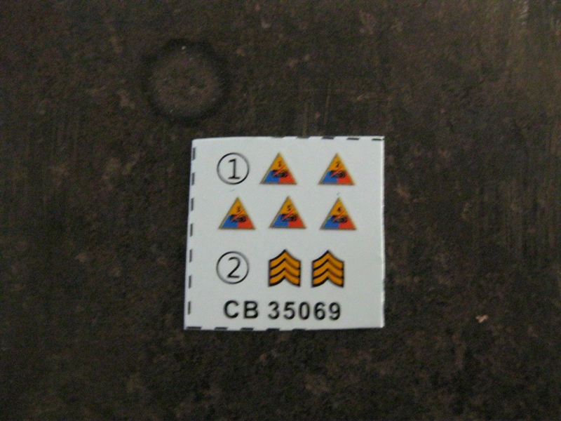
Small decal sheet for the figures, with divisional patch for the 1st armored division, and one set of sergeant's chevrons.
There is also a sprue with .30 and .50 cal ammo boxes molded in one piece, but they are not WWII issue.
the kit
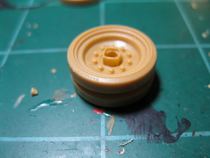
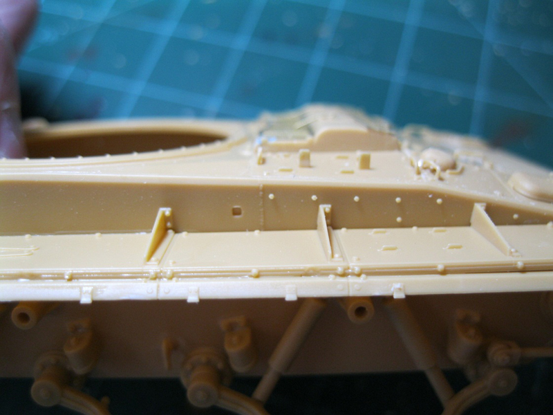
The parts are all very well molded, and detail is excellent. Slide molding has been used on a number of pieces to improve detail. All gun barrels are hollowed out at the muzzle. Casting numbers are present on cast hatches and the fuel valve covers. The rubbery tires have "Firestone" and tire information present on the sides. Every effort possible has been made to provide as much detail as possible to the kit. Small amounts of flash were visible, and some mold seam lines will require some cleanup, but there were no knockout marks on visible surfaces and no sink marks or other blemishes that I could see. Many of the parts are molded very thin and can bend or break easily, so much care will be needed. To eliminate knockout pin marks on parts, knockout "nubs" are used generously. While it takes a little more effort to remove them and clean up the attachment point, it is much better than dealing with even more cleanup of the knockout indentations.
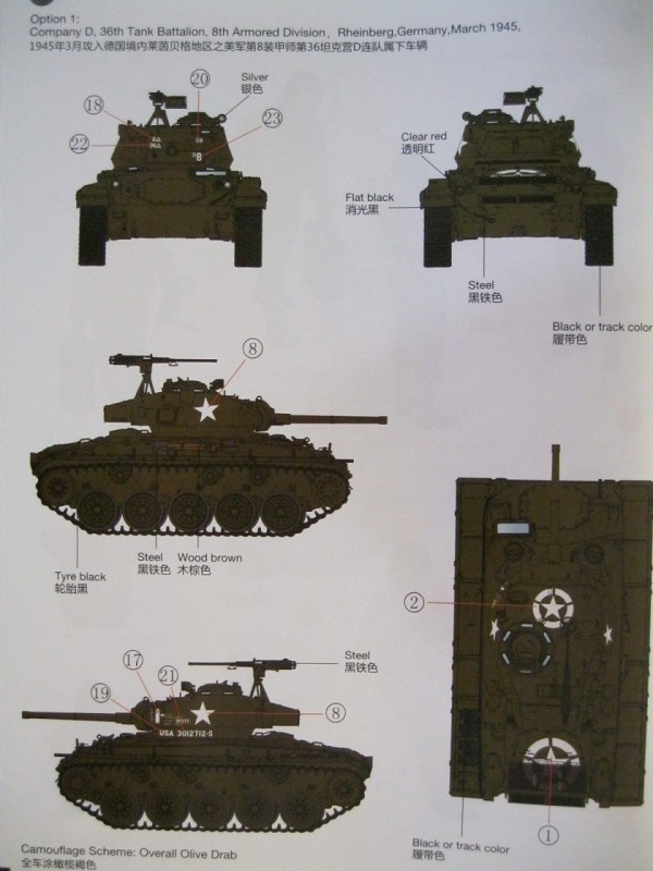
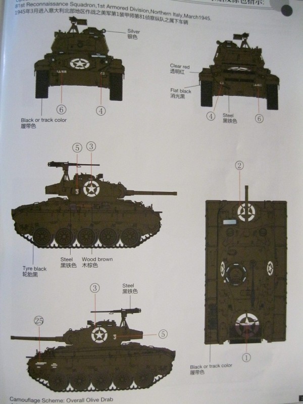
The instructions depict assembly in a series of line drawings, with multiple sub assemblies called out. CAD images are used for photo etch parts to better illustrate what the instructions are trying to point out. There were several corrections in the instructions, with parts numbers pasted over with new number. Assembly is covered in 41 steps, with step 42 showing the completed model. Three marking schemes are provided, with views from both sides, front, rear and the top. All vehicles are in overall Olive Drab. Option 1 is a vehicle of Company D, 36th Tank Battalion, 8th armored division, Rheinberg, Germany, March 1945. Option 2 is for the 81st Reconnaissance Squadron, 1st Armored Division, Northern Italy, March 1945, this vehicle depicted in the box art. Option 3 is for the 37th Armored Battalion, 4th Armored Division, NW Europe, March 1945. Paint colors are called out GSI Creos Mr. Hobby and Hobby Color lines, Humbrol and Tamiya.
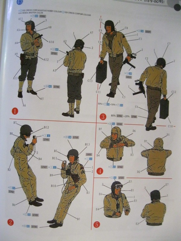
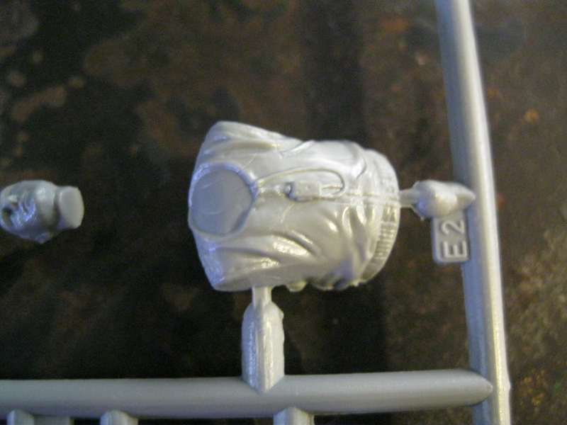
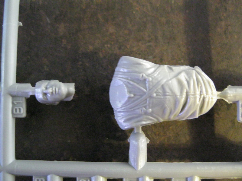
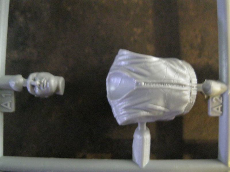
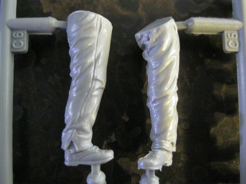
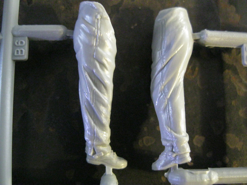
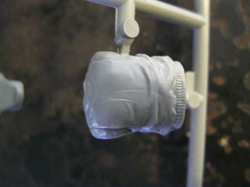
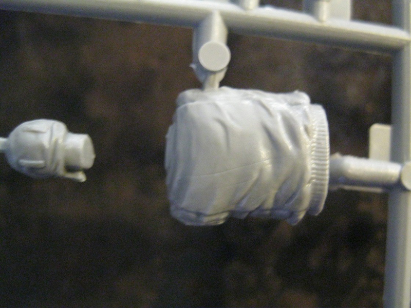
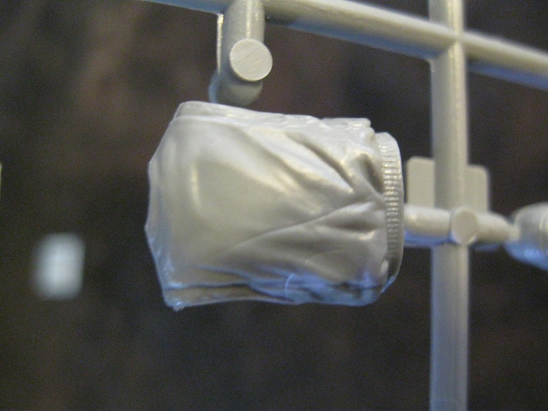
The figures are generally well done, and very detailed for plastic. There are some seam lines to clean up, and loss of detail along the seams and sides. All of the torso sections had 'crazing lines', fine hairline creases that occur when the plastic cools unevenly. Color instructions for assembly of the figures are copied from the Dragon box, showing a drawing of the figure with lines indicating placement of parts. Paints are for GSI Creos Aqueous color and Mr. Color brands and Model Master enamel paints.
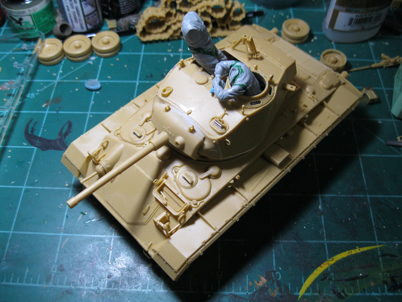
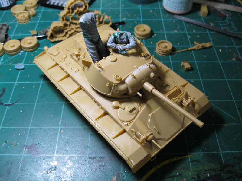
the build
I didn't buy the kit to look at, so I jumped in to the build as quickly as possible. Remarks on the individual parts will be made throughout the build. A quick warning: this kit is not a quickie and it is intended for modelers with at least good intermediate skills. I recommend building with relaxing music in a peaceful location, and avoid the use of stimulants as some of the assembly could be aggravating.
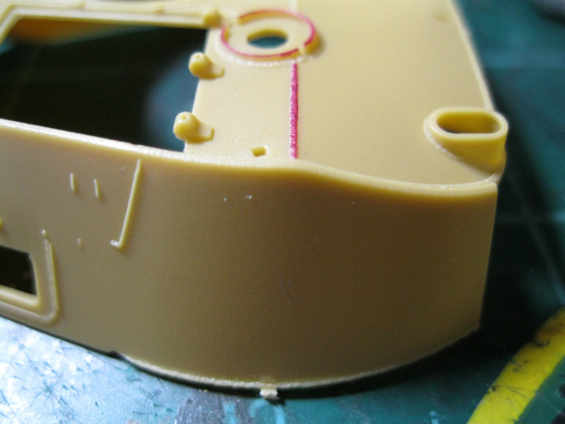
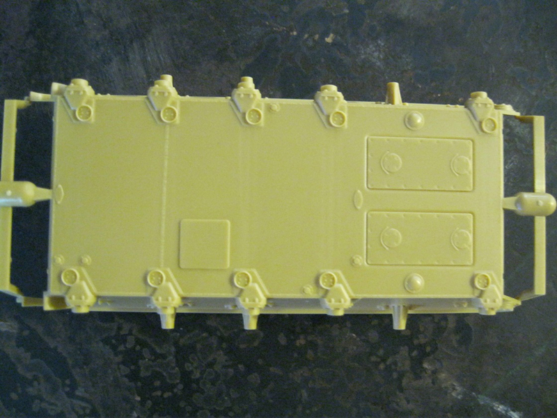
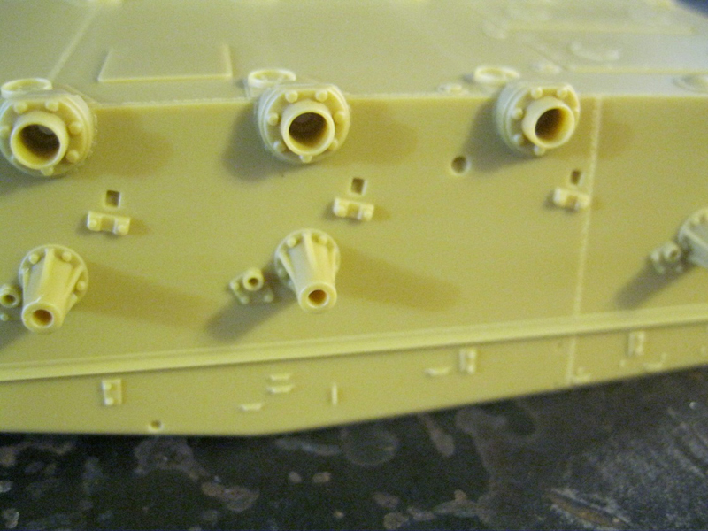
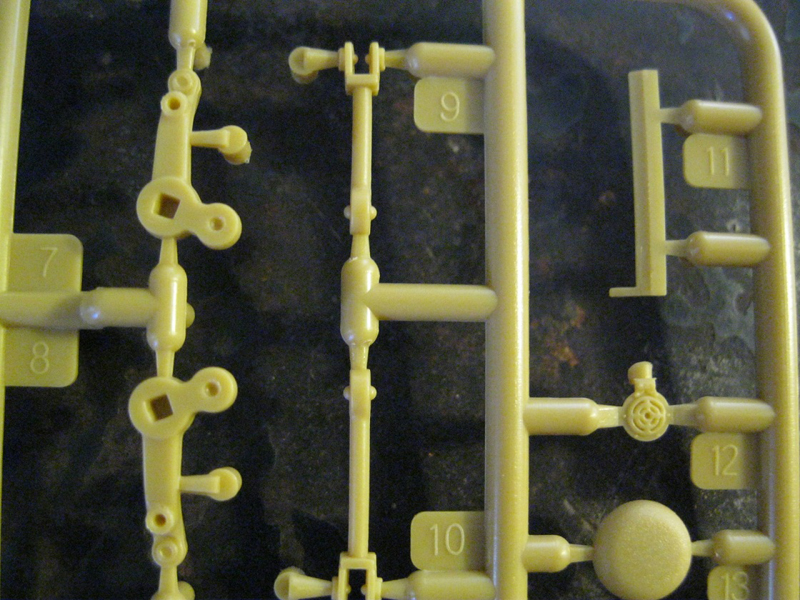
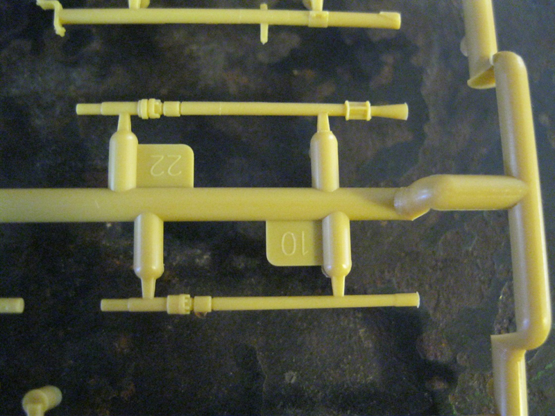
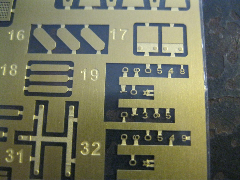
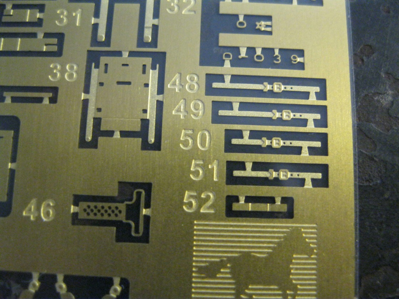
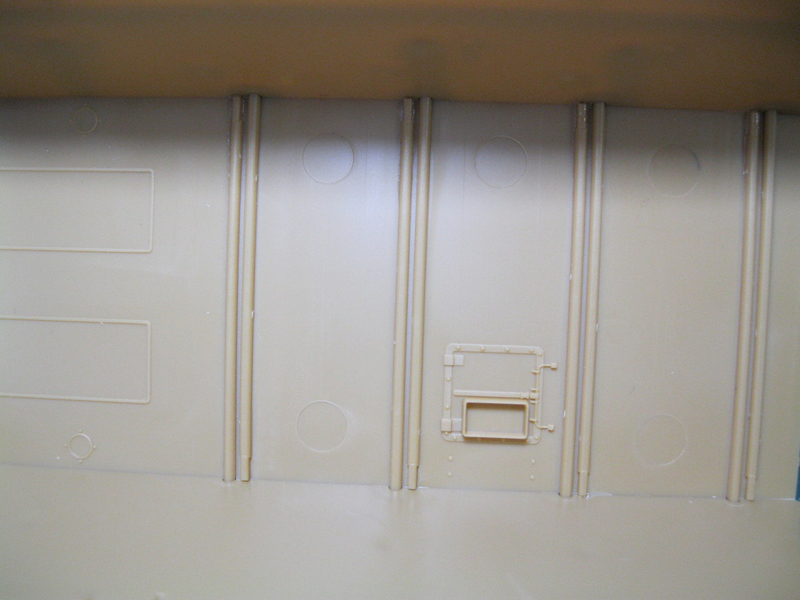
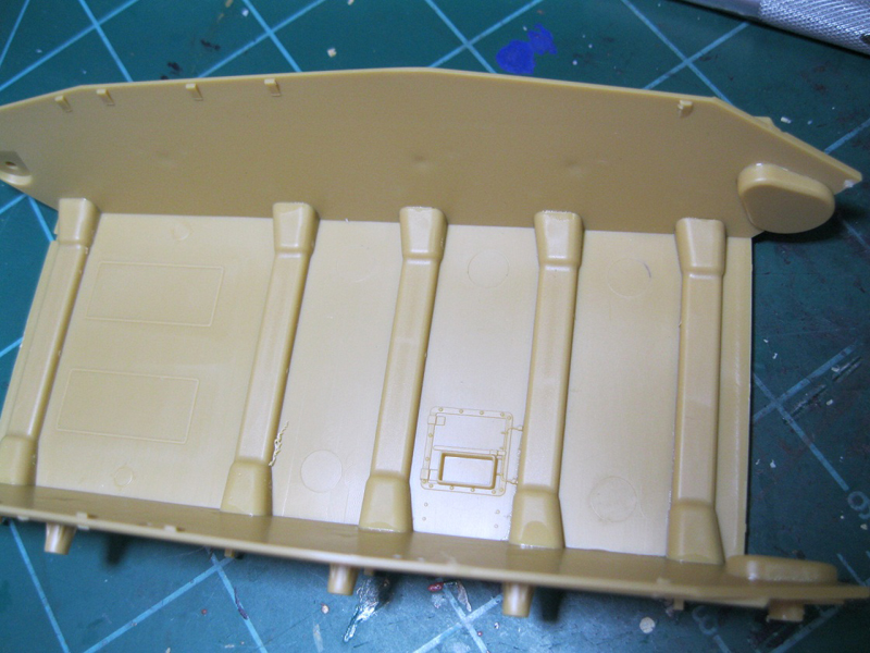
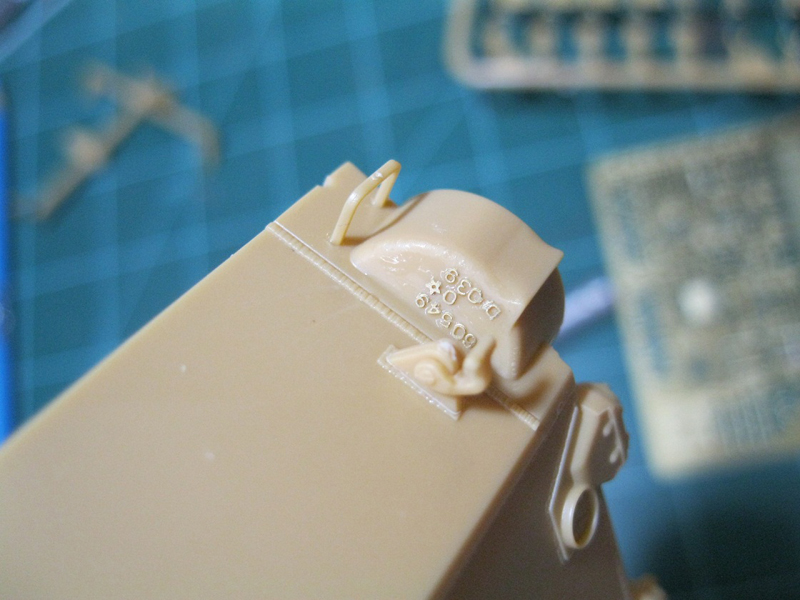
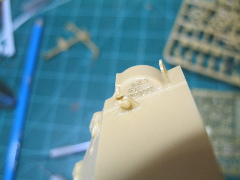
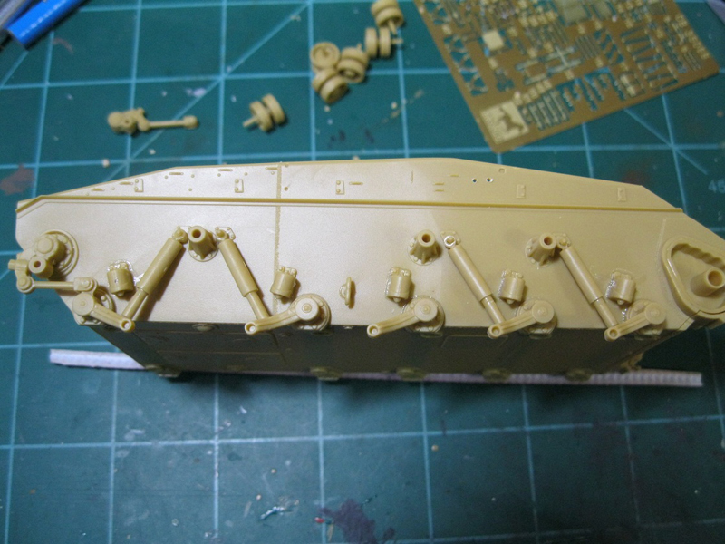
Step 1 is the assembly of parts to the hull tub. Torsion bars must be placed carefully, making sure they are properly aligned so that in later steps, the suspension arms sit properly. To preserve a working suspension, they should only be glued on the inner end. Then the torsion bar covers are installed. Mine all fit without trouble, but test fit for safety. The transmission bulges on the front hull plate get photo etch casting numbers. With all the detail in this kit, I don't know why they didn't make the transmission bulges as separate parts, numbers molded on. As it is, I chose to put a thin layer of CA glue over the part, then carefully add the numbers and letters. I considered, and probably should have started by putting some regular thin cement down, then placed the numbers on the tacky surface, and then put the CA glue over the top. As it was, I only messed up a "1", which looks like a metal sliver. As an option, if you have some spare sprues with extra letters on them, that might prove easier. This is an area that I'm sure some aftermarket folks will jump on. Also, the second line of the casting reads "1O", followed by a star. The "1" for the second transmission bulge is not included in the fret. Other online photo sets of the fret all show the "1" missing as well. Almost any sliver of material will work to replace it. The inner final drive sections for the drive sprockets are also placed inside the hull, before the front plate.
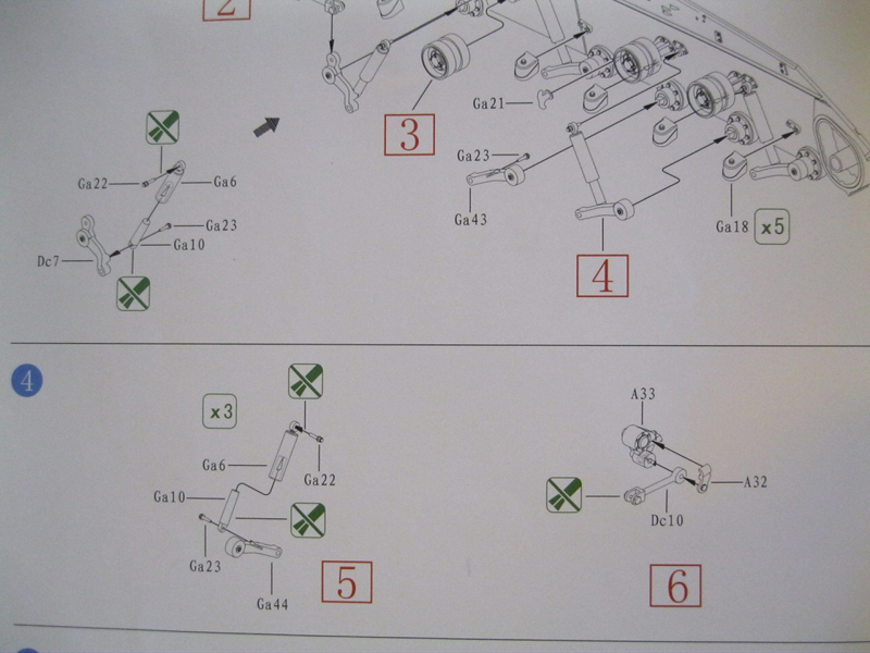
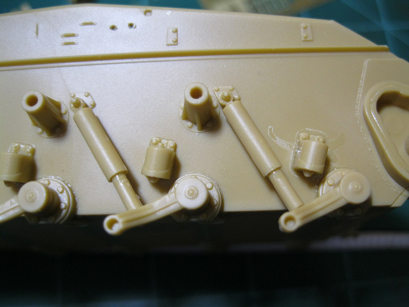
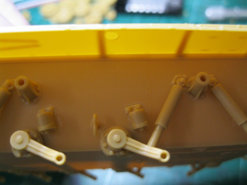
Step 2 has three sub assemblies. These create moveable parts for the idler wheels, road wheel struts and the return rollers. The idler assembly is easy. The road wheel struts leave a very small pin loose so I opted to build these with the main assembly. There are a total of 8 return rollers included on the sprue, with only 6 being used in this kit. Apparently, Bronco are planning ahead for the various gun motor carriage vehicles based on this chassis. The assembly instruction says to not glue the inner pin, allowing the wheel to rotate freely. If you are really careful with the glue you can get this to work. However, you will also need to ream out the hole as when I inserted the pins they went through at an angle.
Step 3 attaches the road wheel struts and rear idler to the hull, left side. Again, with extreme care with the glue, the small pins that attach the struts to the torsion arm and the hull will allow the parts to move freely. However, the pins are very small and somewhat delicate. The struts, if cleaned up, will move freely, but also flex. The entire assembly is very spindly and won't sit with any stability. You can pose the suspension in the attitude you want, but for me it was best to fix everything in place once it was where I wanted. If you want the vehicle sitting level, Steven Zaloga has stated over at a discussion on Missing-Lynx that the proper height is 11mm from the hull bottom to the bottom of the road wheel. Bump stops for the torsion arms are also added to the hull, along with a tie down.
Steps 4 and 5 repeat the above process for the right side of the hull.
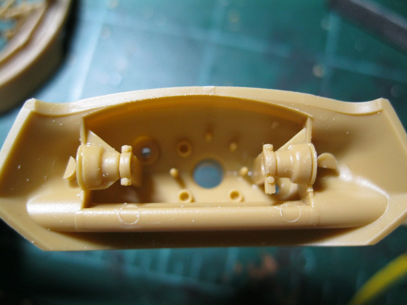
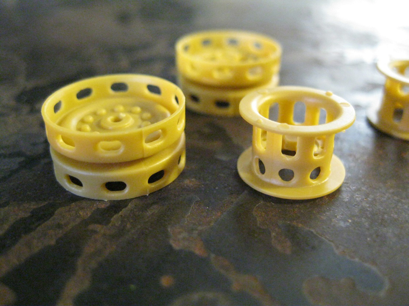
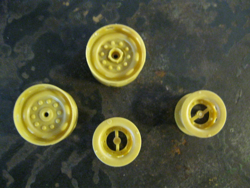
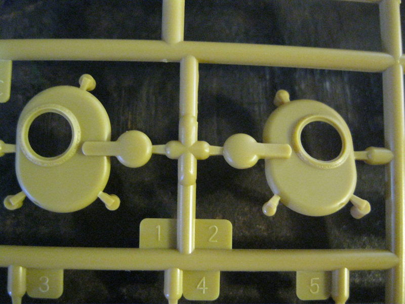
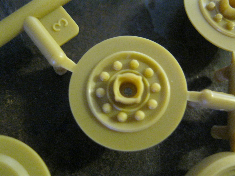
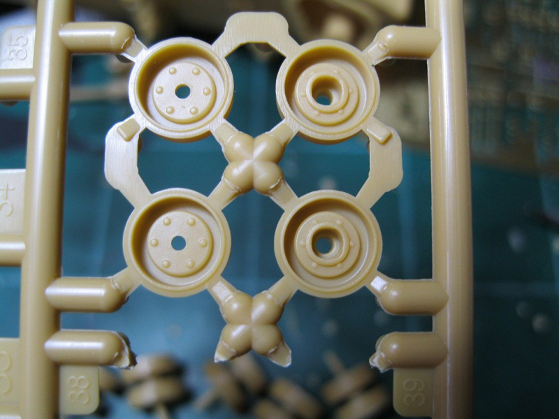
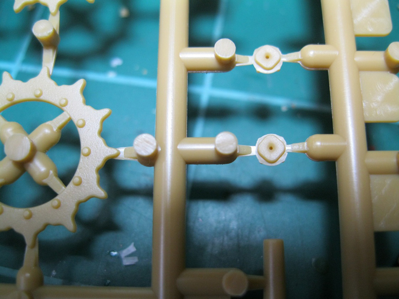
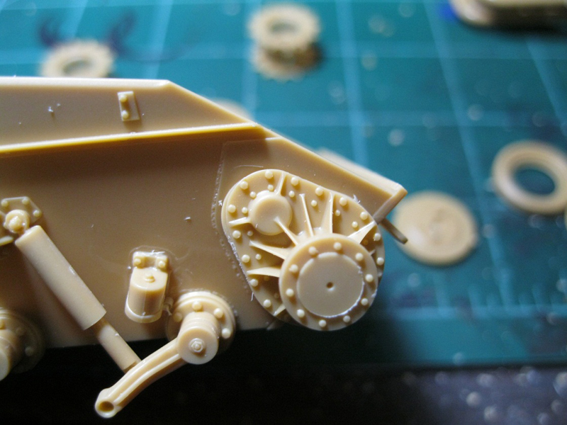
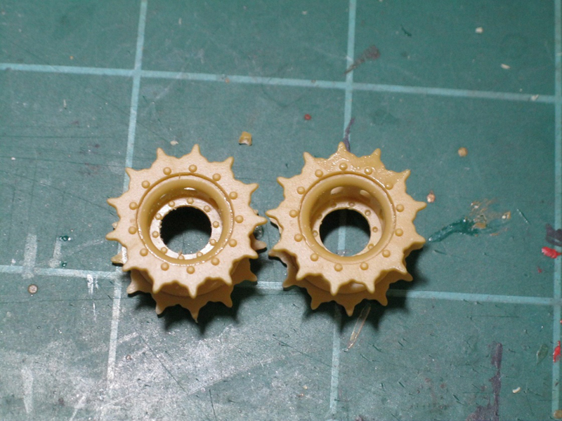
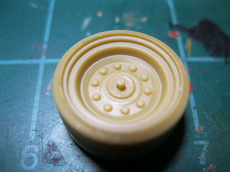
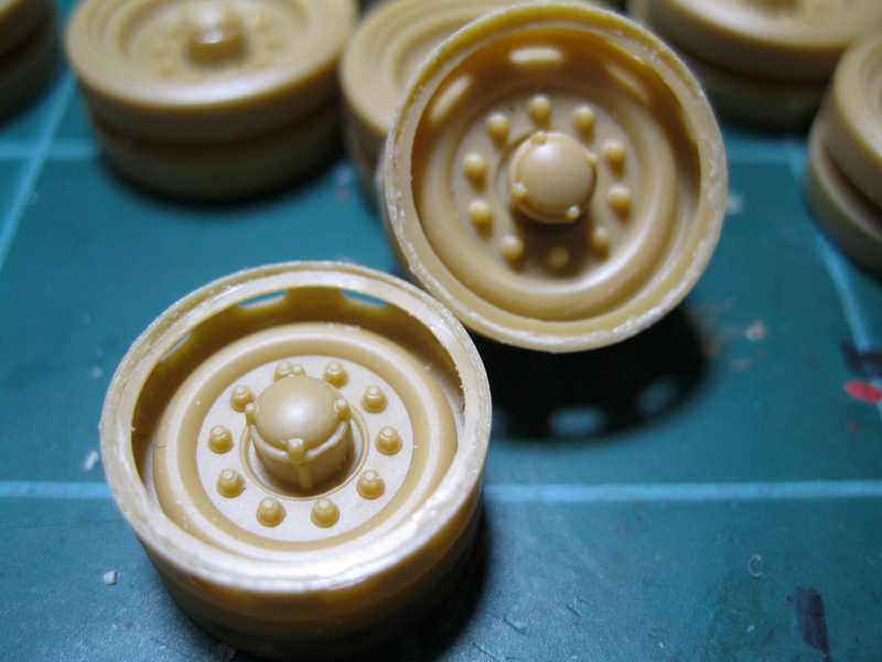
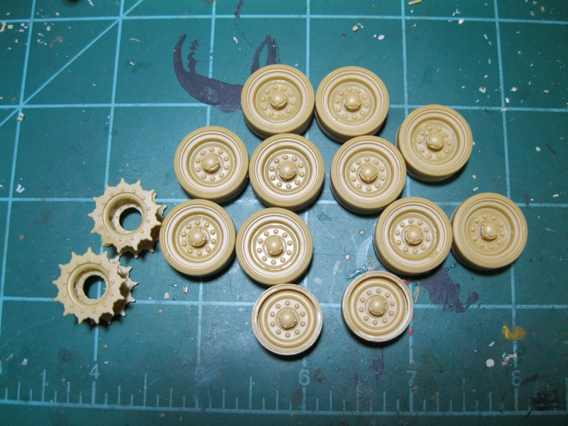
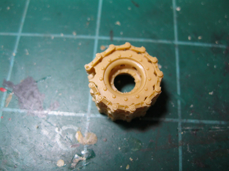
Steps 6 and 7 assemble the drive sprockets, road wheels and idlers. The inner hub of the drive sprocket is carefully slide molded as a single piece, with lighting holes (I learned that from Frank DeSisto) cut out of the hub. Detail is excellent and will require only light sanding to remove seam lines. A pin is inserted into the final drive housing but is not glued. This is inserted into an inner flange that is then inserted into the drive sprocket hub. The parts were all a tight fit and needed some light sanding to go together well. I only attached the flange, leaving the drive sprocket off until final assembly.
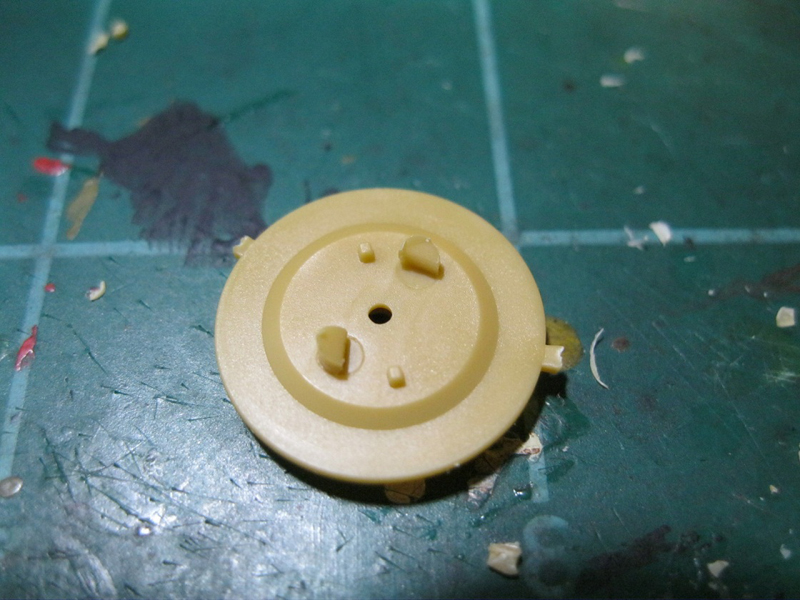
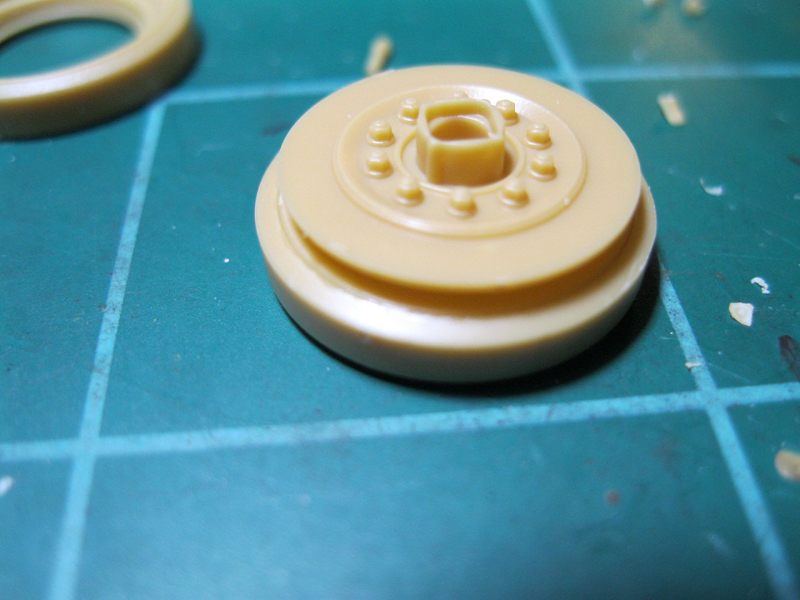
The road wheel inner wheel surfaces both attach together at the back, and then the outer rim and tire attaches to the inner wheel. Then a small pin is inserted and a hubcap carefully glued over that. Again, the pin should allow the road wheel to move freely. The pin only protrudes a small bit out of the wheel assembly, and fit to the torsion arm is poor, so I didn't try to preserve a movable pin for this part.
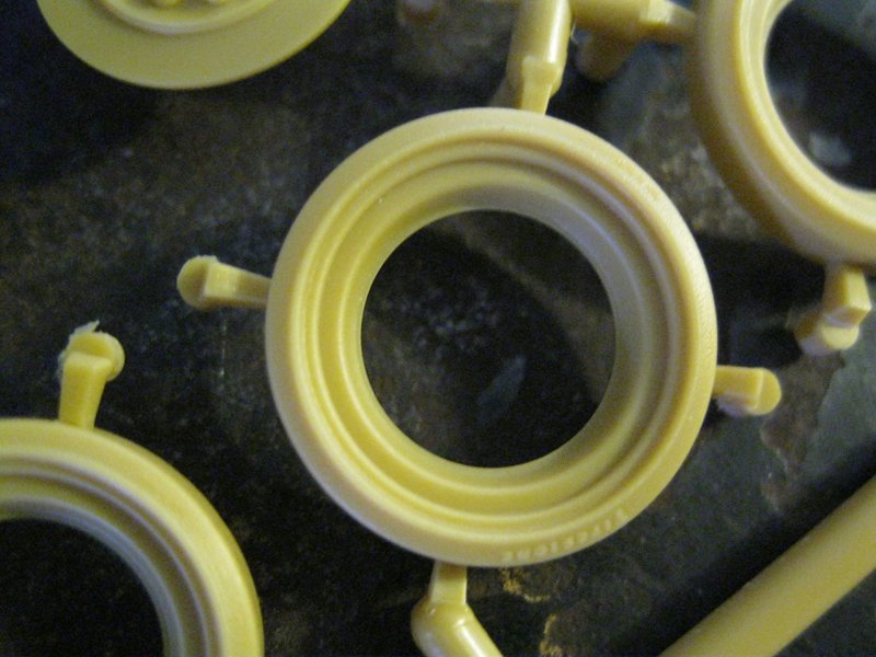
The idler wheel is again slide molded with the lighting holes around the surface. There are small rims to insert, creating a slight inner lip. After test fitting it appears the rounded side is inserted into the wheel, with a slight edge extending past the inner rim. The same pin and hubcap are used as with the road wheels, with the same poor fit to the torsion arm. Again, these were left off for final assembly after painting.
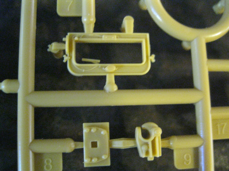
Step 8 is assembly of the driver's foul weather windscreen. Placement of the bracket was not specific enough so I assembled this on the glacis section. There are some tiny etch bits to place, two of which are supports for the windscreen. I left the clear part out until after painting.
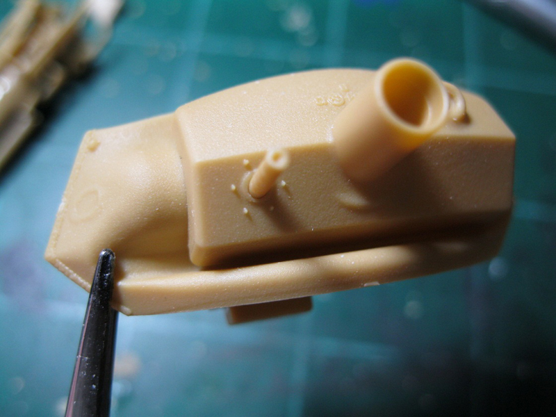
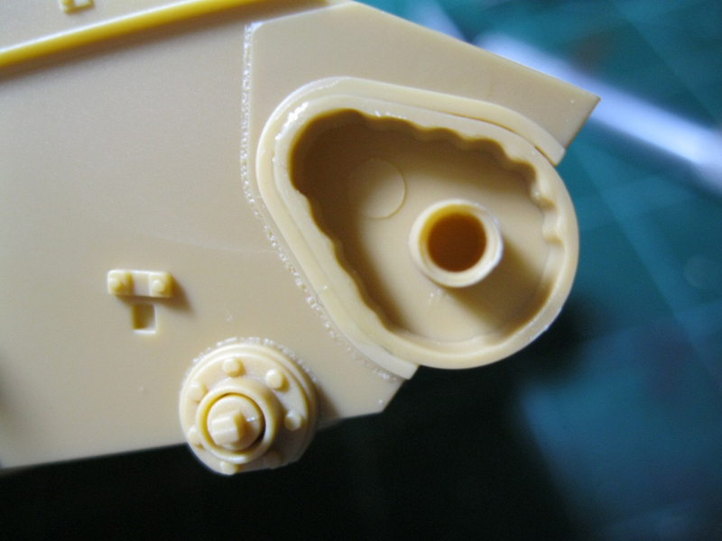
Step 9 is the option of etch or plastic brush guards for the headlights. Plastic forms are included to bend the etch parts into shape. After several attempts with the etch and some really old CA glue, followed by some frustration induced forcing, I went with the plastic options. The lights are slide molded and very well detailed, with clear lenses as separate parts. A blackout light is included as an option. The horn face is a separate part with fine detail.
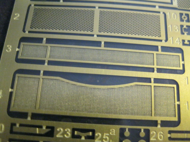
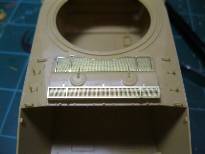
Step 10 places etch screens over the intake vents on the engine deck. New CA in hand, I attached the screens to the deck, and then added very small hinge details. These are a part to bend into shape, with no indication of where to make the bends, and two tiny pieces that make up the sides of the hinge bracket. They are small enough that I didn't bother with them, mainly because I couldn't see them without significant magnification. A nice touch in the instructions was that there are small drop boxes with a magnified view of how the hinges attach, and a small cad image of the completed hinge.
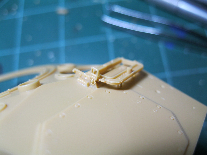
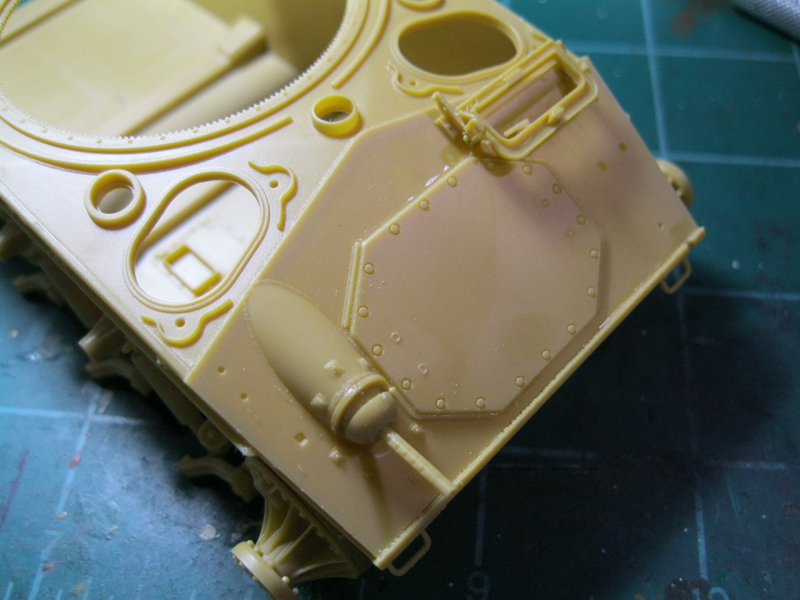
Step 11 adds parts to the glacis/turret ring section. Parts Ga32 are the hinge attachment for the hatches. Don't glue these until you place the hatches, so that you get them where you want. The transmission access panel is a separate part, but to leave it off you need a kit interior. The bow MG is made to be movable with careful assembly. There is a small lip against which the inner bracket, parts Cd1 and Cd10, should rest. Then the ring, part Cd14, goes over that. The ball cover, part Cd12, attaches to the barrel of the gun. The problem with the assembly is that the opening for the gun in the inner bracket, Cd10 and 11, allowed the gun to pass completely through, offering no retention. I chose the angle I liked and fixed the gun in position.
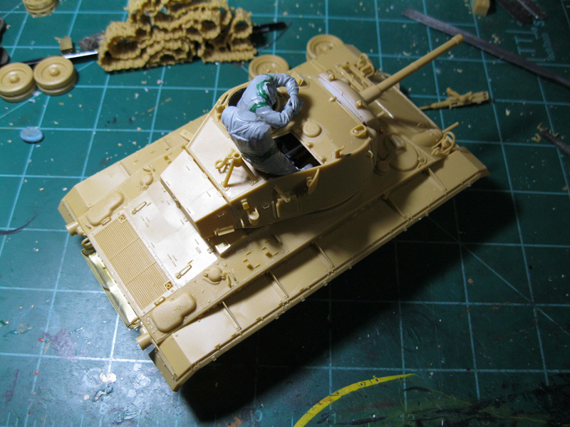
Step 12 puts grab handles on the sides of the rear engine deck. These parts attach to the screened over air intakes, making one section of the rear deck plate.
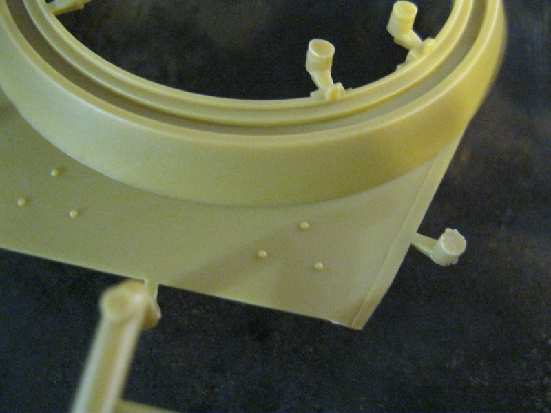
Step 13 attaches the glacis/turret ring section and the rear engine deck sections to the hull tub. I put the sub assemblies together as one section, and once the glue had set a little (but was still flexible) I placed the part on the rear of the turret ring, shaping the part. There are two tiny attachments to the hull side, stops for the open hatches. They are GA4 for the right side, and GA1 (not Ca1) for the left side.
The next series of steps in the instructions show several sub assemblies, not in order, then placement of the assemblies on the kit.
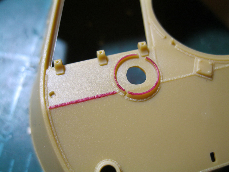
Step 14 assembles the periscopes in the rotating port and placed them in the two hull hatches. The instructions show not to glue the rotating port, indicating that it will turn, but the part is not retained at all, so to keep it with the kit, you will need to glue it.
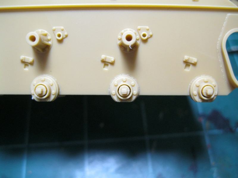
Step 15 assembles to two rear fuel vent sections of the rear deck, with fuel caps and the cast vent covers.
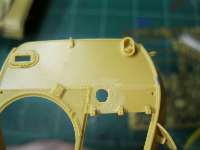
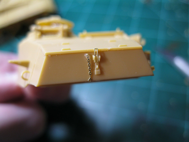
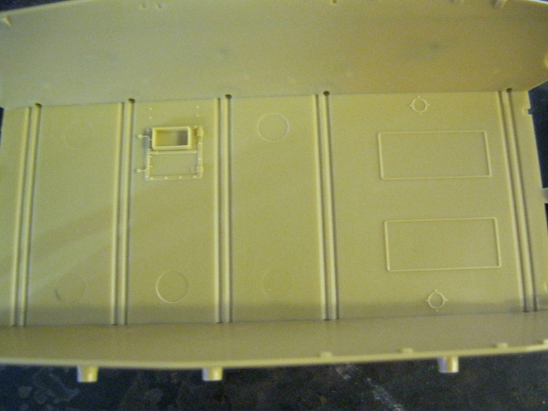
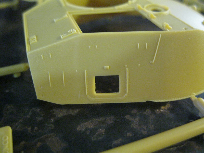
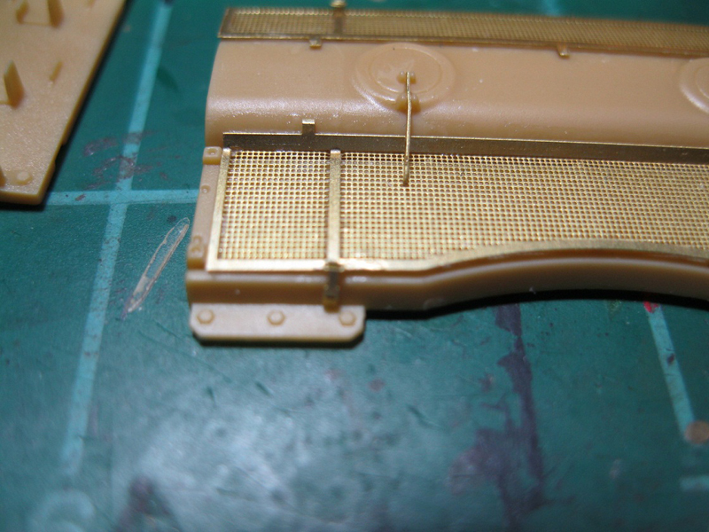
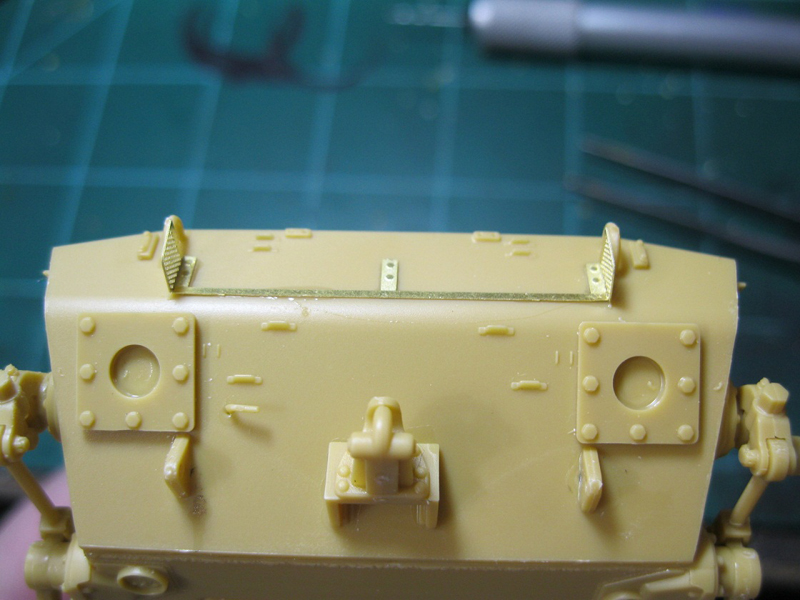
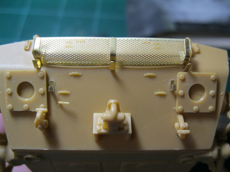
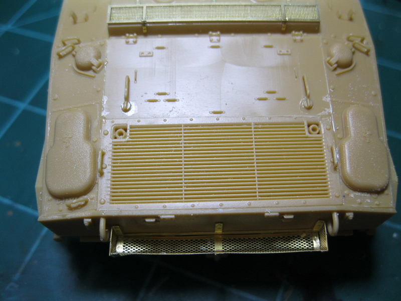
Step 16 assembles the rear hull plate. There is an etch mesh basket that goes on the plate. It is two sections, with the inner part having the two sides and the bolt strips, and the outer section being bent to make the basket body. There is no mark indicating where the bend should be made, so I measured three times, made the bend and then put it on. There are faint surface marks on the plastic showing where to place the inner bracket. The instructions show to round out three holes on each side.
Don't. Two are already round and don't need fixing. The third is square, and should remain square. Tow hooks, rings, a hitch and two square flanges are added to the plate for detail.
Step 17 attaches the hull hatch covers to the hull. This is where placement of the hinge bases is critical, and why they shouldn't be glued in place until this step. There are also two locks per hatch, each getting its own tiny etch handle. Placement is not clear in the instructions, and I couldn't find photos of these parts, so I guessed.
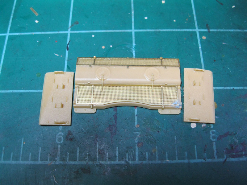
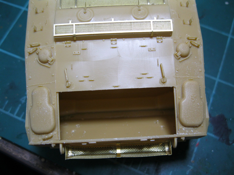
Step 18 completes the rear engine deck. Exhaust nubs are installed on the vent screen, handles and tie downs are attached and the sections are added to the fuel vent plates. I added the rear hull plate first, and then the vent sections and solid engine deck plate, checking fit of all parts. I ended up needing to sand the vent plates to shorten them slightly in order to get a good fit. I was then able to test fit the exhaust screen, again sanding it down to get it into place.
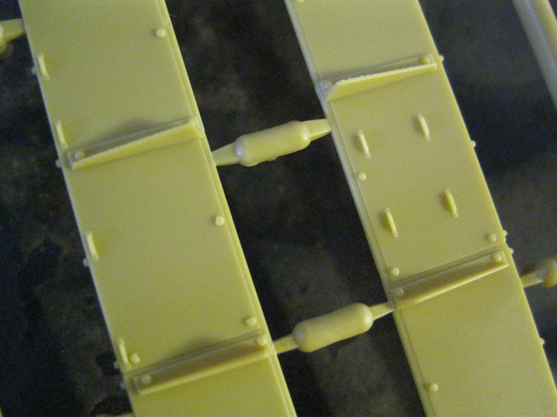
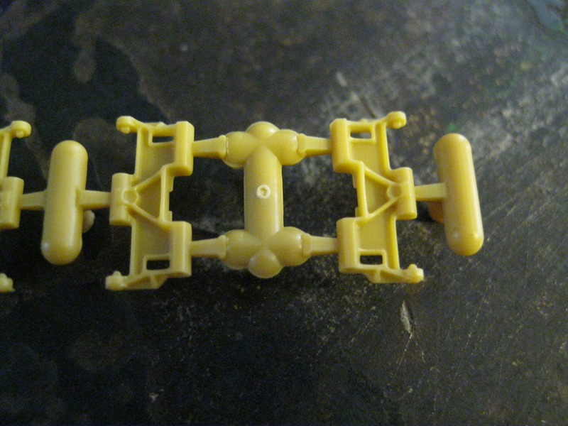
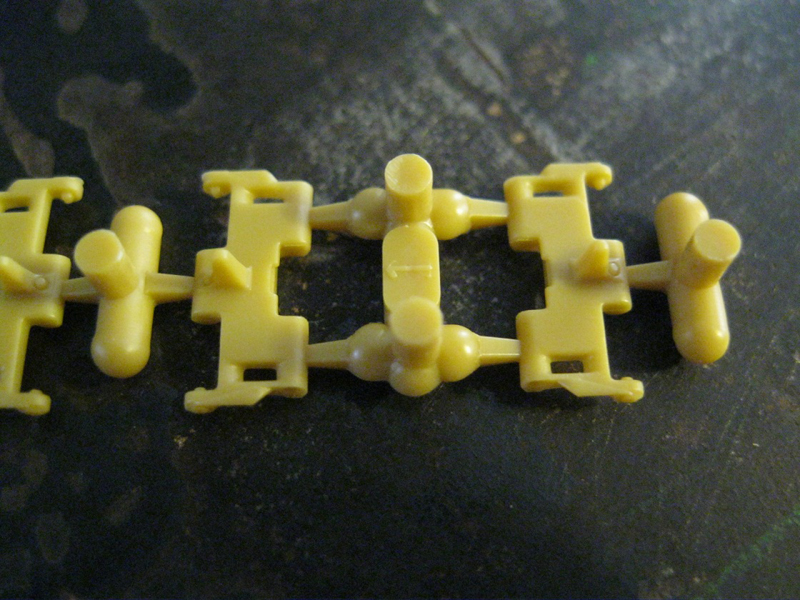
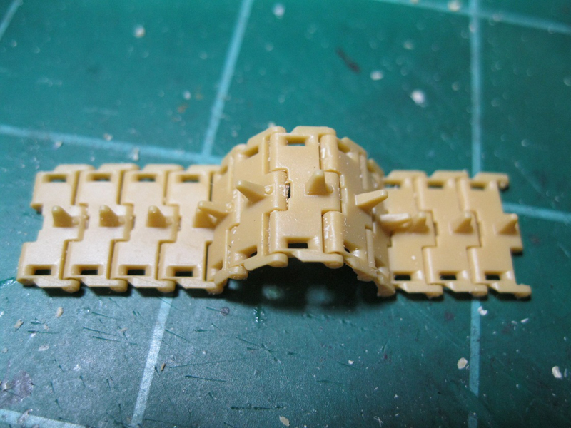
Step 19 assembles the tracks and placed them on the running gear. I built the tracks to test fit to the sprockets, and then set them aside to wait until final assembly and painting.
Step 20 is assembly of the track guard, sand shield bracket and sand shield for the right side of the tank.
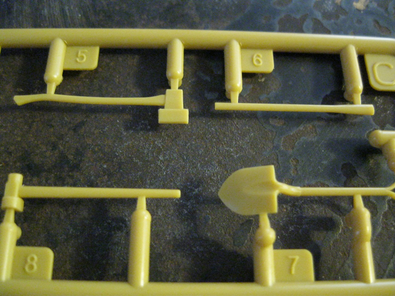
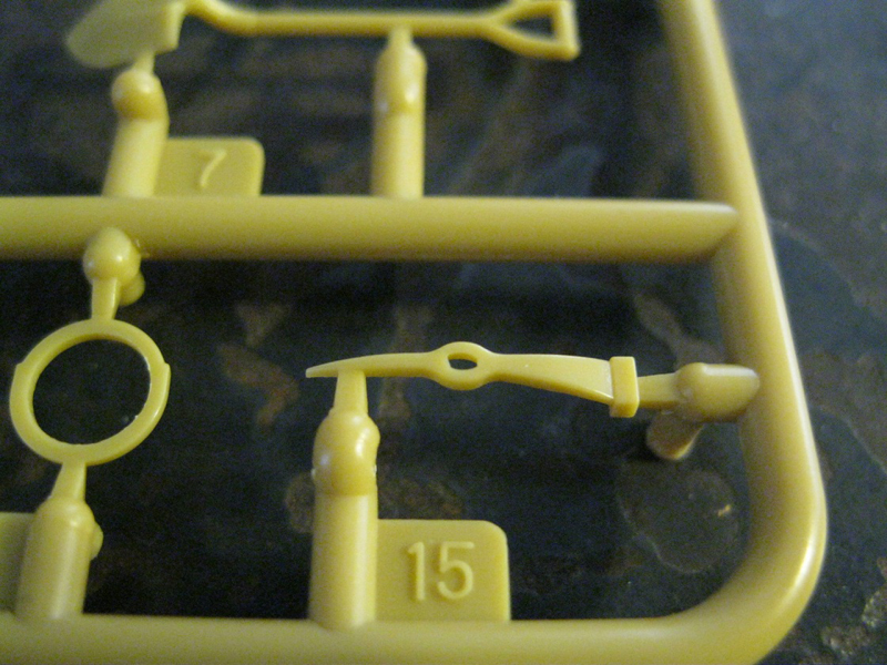
Step 21 adds tools, with no molded on bracket or clamp, and etch straps. This is a very nice detail for the kit. I skipped this step for final assembly.
Step 22 adds a shovel and sledge to the other tools.
Step 23 assembles the track guard/sand shield for the left side. The string is attached to the tow cable eyes, but these will need to be drilled out. Four spare track links are added to the track guard. I only added the track guard and sand shield strip, waiting for final assembly again before placing the sand shield, if I use it.
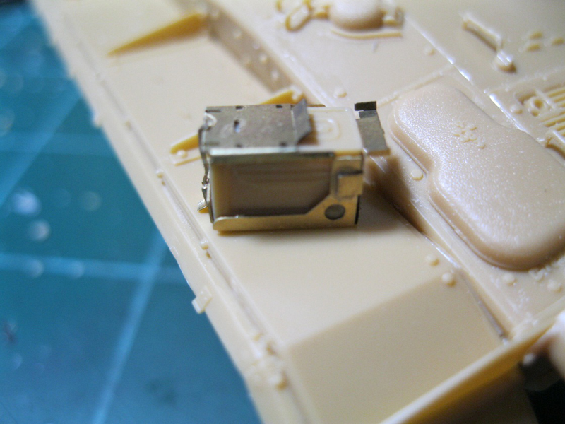
Step 24 attaches the track guard to the left side of the tank, and adds a box (phone or first aid) to an etch bracket, bends are again estimated, and also three cable clamps to the side of the hull. There is a cad image of the etch parts, and the clamps are supposed to be bent into a corkscrew shape. Also added here and on the other side are rear lamp brackets. They are molded such that the inner lamp assembly appears to be a separate part from the outer lamp assembly.
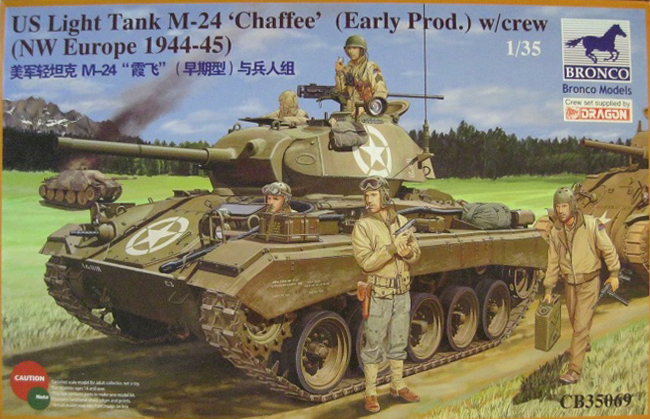
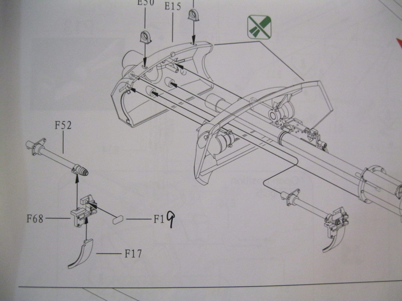
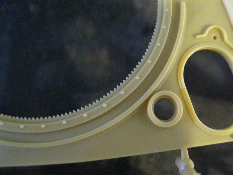
Step 25. Herein begins the assembly of the main gun. Again, patience. I referred frequently to pictures of the completed assembly, and I think this area was poorly thought out. The first half of this step is best left until you attach it to the main gun assembly in step 27. Sub assembly 23 places the trigger mechanism along the side of the gun mount base. The breech guard attaches to this at one point, and is very flimsy. Part F72, the rear plate of the breech guard, is shown upside down. The other half of this step attaches the turret ring base to the turret lower half. Be careful with cleanup of the turret inner ring as there is a small locator pin that you need to keep for the turret hydraulic pump and handle.
Step 26 assembles the main gun to the recoil spring and breech assembly. The main gun is bored out at the muzzle, but the rifling is very heavy compared to actual guns. If you use the plastic spring, slide it over part E4, then glue E4 to part E3. Then you can attach the recoil mechanism, E9 and E10. I used thick cement on the outside of this part to keep it from seeping in through the cracks. Then the three part breech block was attached. The breech block is again nicely detailed, certainly enough for what will be seen if the hatches are open. Once this is done, I attached part F4 to the base of the recoil housing, then part F35 from step 23 to that, and then the trigger assembly. Then the breech guard was put in place. Step 27 also shows a sub assembly for part of the turret traversing mechanism, which really should go with the next two steps.
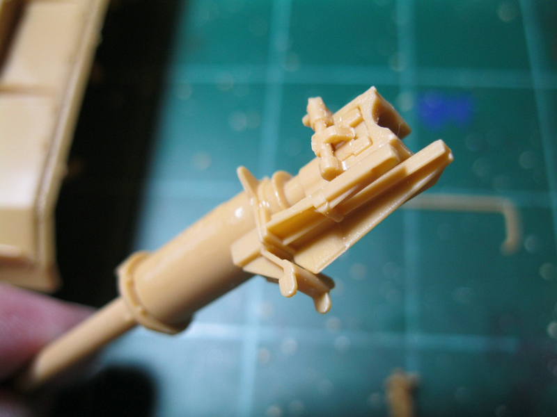
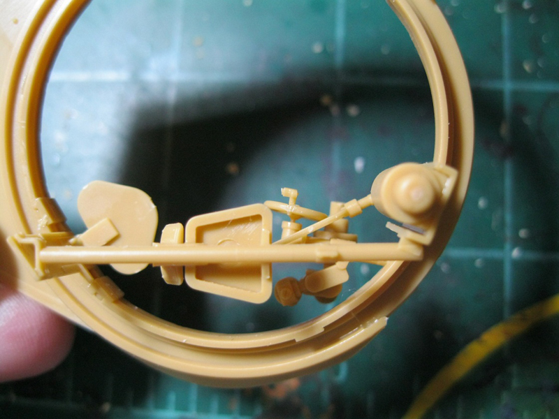
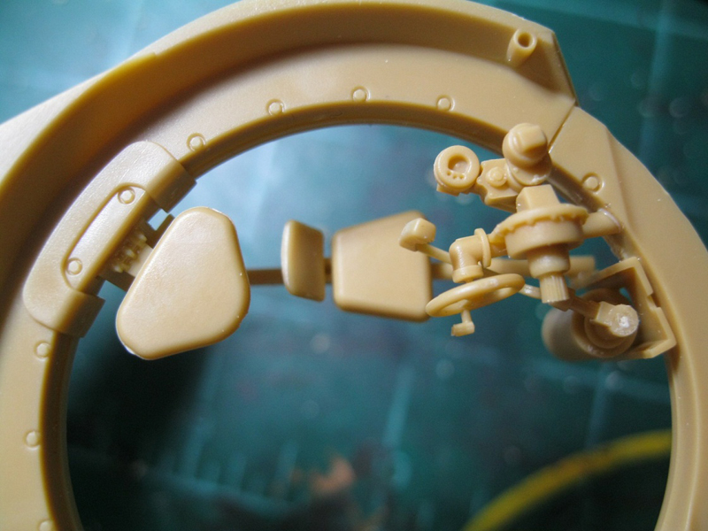
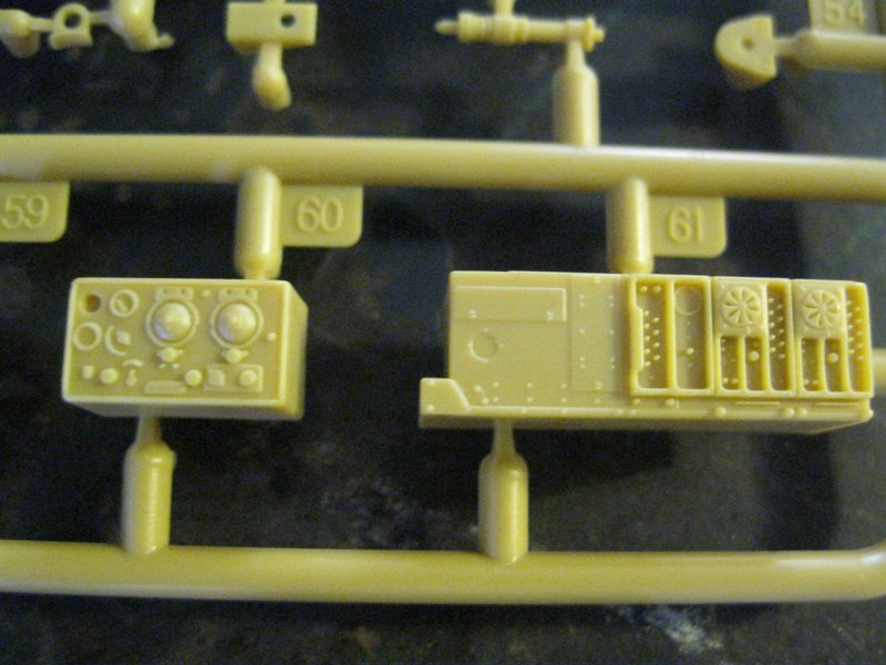
Step 28 assembles the gunners controls and seat. There is an etch foot rest for the seat assembly that I left off until completion as I would otherwise probably knock it off.
Step 29 adds these assemblies to the turret lower, along with two other seats. Attaching the seats and the traversing mechanism is a balancing act, with all three helping position each other.
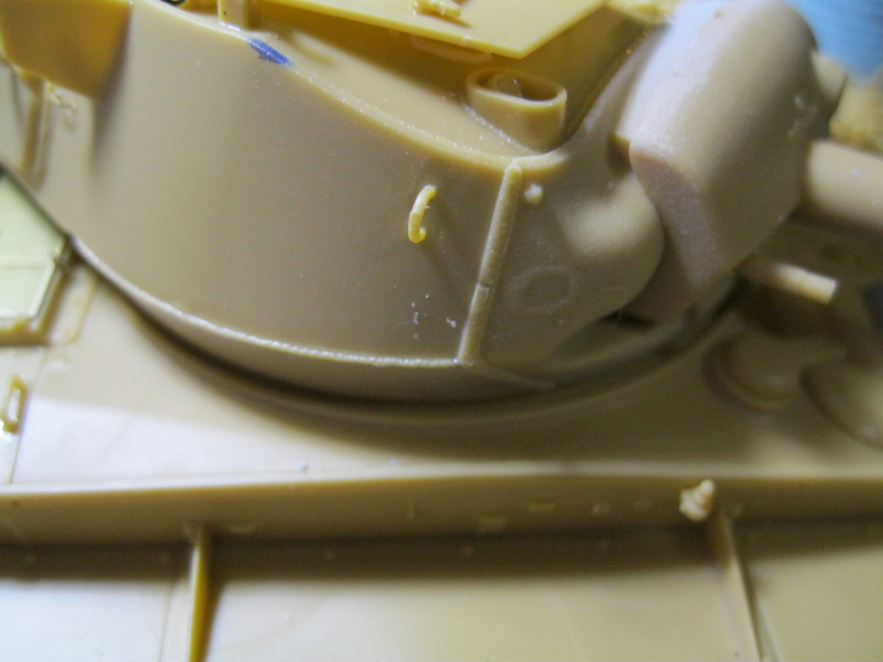
Step 30 assembles the coaxial MG. I did not add the inner braces that attach to the mantlet at this point because there was nothing to hold them to. The snaps for the canvas cover on the coaxial MG should be rotated slightly counter clockwise. I was going to address this but forgot. See the link below for a discussion on this and another issue.
Step 31, I glued the braces, parts F63 and 64, to the mantlet, and then slipped them over the pins of the rotor shield. Once that set, I added the main gun, then the coaxial MG, and then the sight. There is a small locator pin on the end of the sight at the sprue attachment point. Don't cut it off. The gun recoil gimmick should work, but I found it didn't spring back. It simply allowed me to move the gun forwards and backwards. Also, it allowed the gun to rotate slightly, twisting in its housing.
Step 32 attaches the rotator shield to the lower ring. If you attach the turret upper first, the gun breech won't fit through the opening. You have a choice of two radios to add to the turret rear.
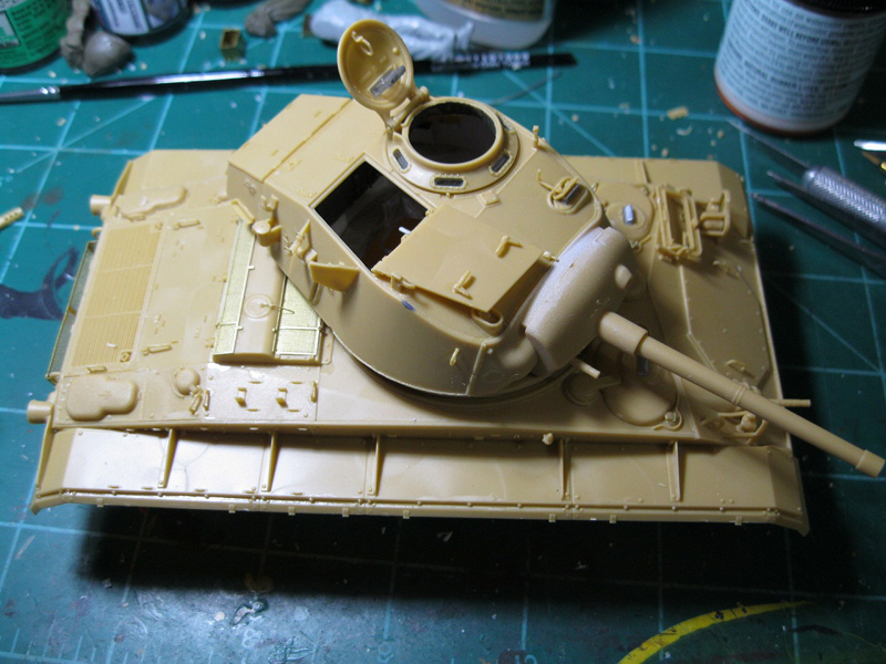
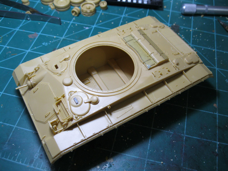
Step 33 deals with the turret upper. There has been some discussion on the turret, see:
Some Mistakes
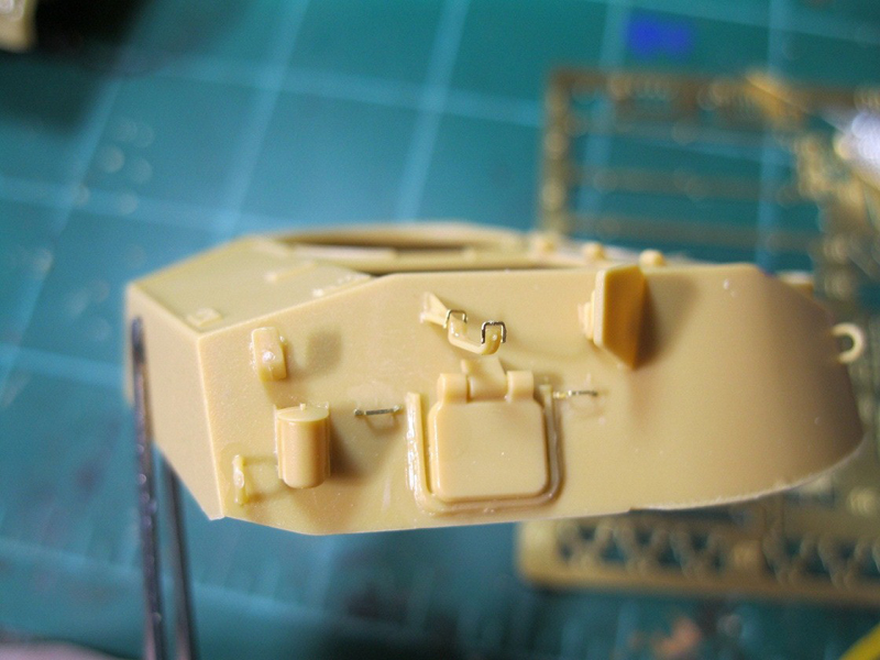
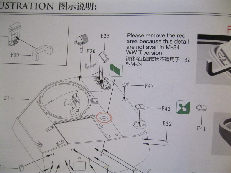
Basically, on the turret roof, the kit shows a weld line along the bend, all the way across the turret roof. On the real tank, the bend is a couple of inches in front of the weld line. It is easy enough to remove the weld line that should not be present, but if you start messing with the angle it's going to be a major restructuring of the entire turret. The splash ring around the ventilator is shown to be removed as it was not a feature on early M24s. There are a number of attachments for the right side of the hull, and two options for the smoke mortar. The smoke mortar must be inserted from the inside of the turret as it won't fit through the top. The pistol port can be positioned open or closed, but here appears to be a part missing that the handle should go into. It is shown extending down from Part E7. I couldn't find it. I didn't install the spotlight, which has a clear lens insert, as again, I will probably knock it off during assembly.
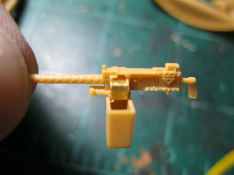
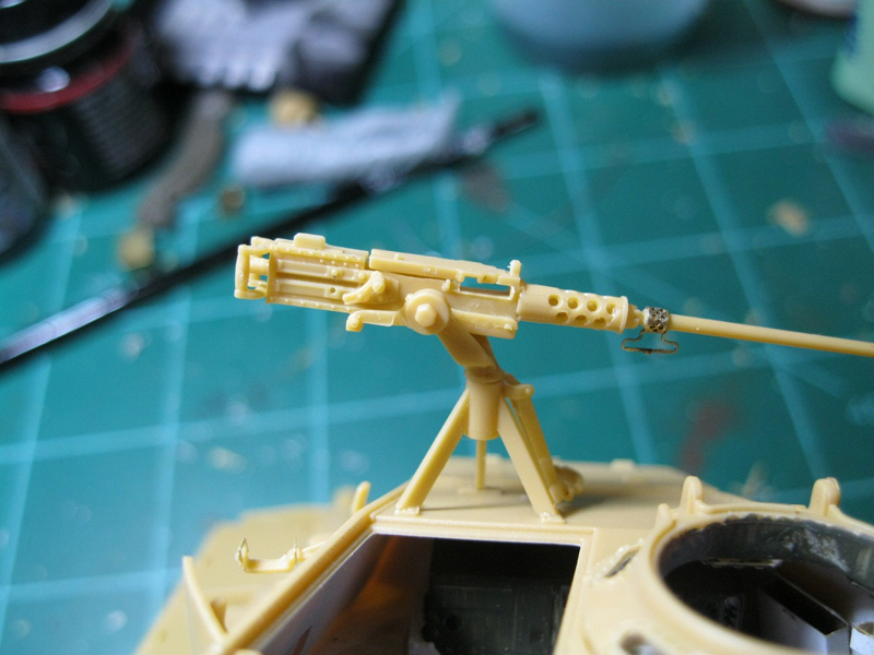
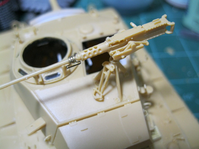
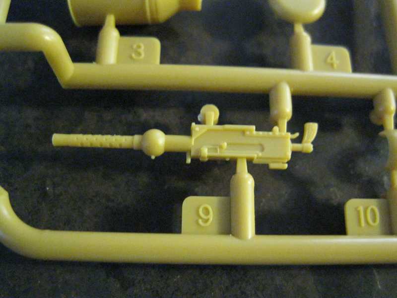
Step 34 assembles the base for the M2 .50 cal MG, and then the gun itself. If you add the etch carry handle you will need to sand down the handle slightly as the etch part won't fit all the way around. The barrel also wouldn't sit straight and took some slight pressure to get it right.
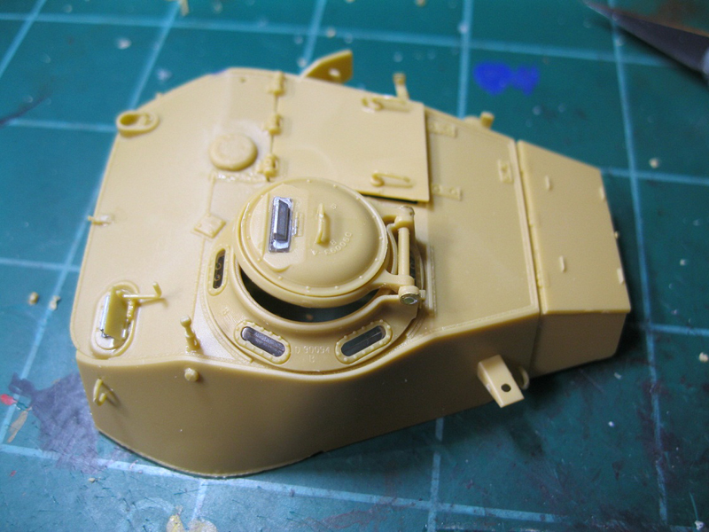
Steps 35 and 36 are again oddly ordered. The loaders hatch is first, with inner and outer handle detail. Then the rear turret stowage box, and then the commander's cupola. I would have thought the hatches would go together. the commanders vision cupola has clear inserts for the all around periscopes and the main hatch periscope, which again is shown as not being glued so it can rotate. Again if not glued into place, it will fall off, and mine wouldn't sit straight, so I had to fix it into place. Both hatches can be positioned open or closed.
Step 37 wanders off, assembling a .50 cal ammo box and etch holder to go with the previously assembled gun. If you desire, there is a plastic version with molded on ammo belt, but the instructions for assembly are not depicted. The hatches, vent cover, lifting rings for the left side of the turret, tool box and ventilator cover are placed and the upper turret set on the lower turret ring. The instructions show to stretch a sprue to get the antenna although no length is given. The completed turret snaps into the turret ring on the hull, and rotates freely, as shown in step 41.
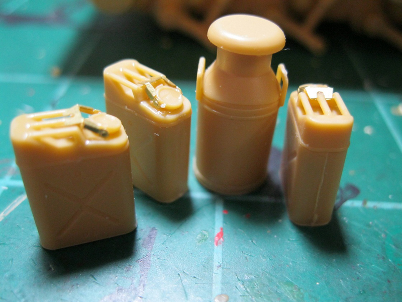
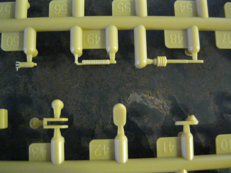
Finally, assembly of the milk jug, which is a nice and unique accessory. It is thinly molded and could be shown with the cap off. There are also six 5 gal jerry cans, with raised bead detail between the upper and lower sections. You have an option of etch or plastic clips for the cap. The .50 cal ammo boxes are made up of 6 parts, with good detail on all surfaces, and include decals.
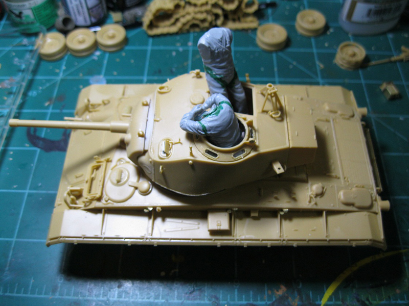
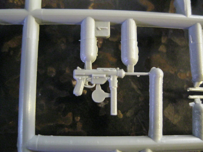
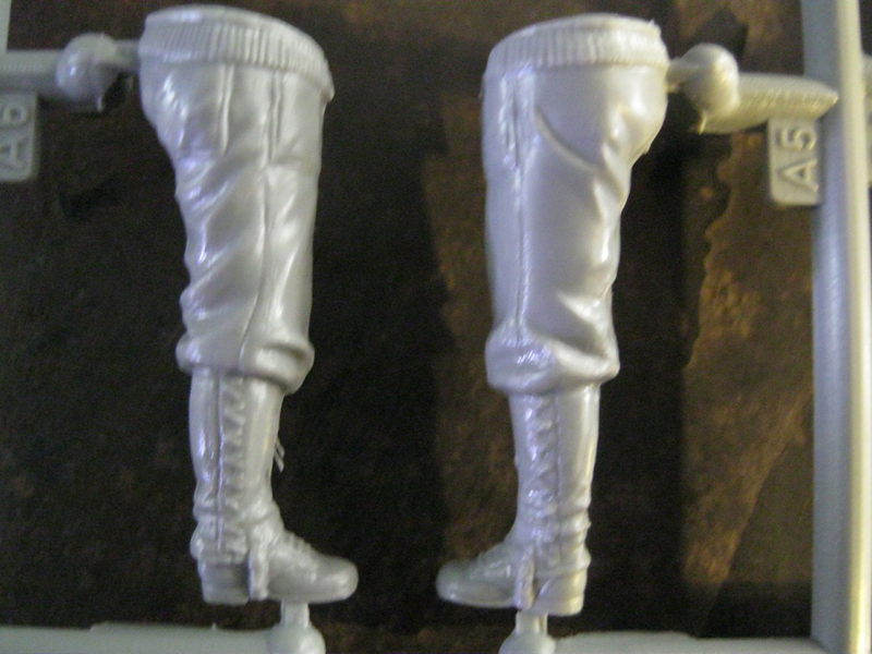
The figures from the Dragon set are three full figures, one tank commander on the radio, one crew member standing with a .45 in his hand, possibly loading it, and one unhappy guy lugging a jerry can and shown with a well detailed M3 smg. The driver and loader are shown as half figures. They are multi part assemblies, with separate heads, helmets, collars on three, holsters, arms, and for the complete figures, separate legs. Some gap filling was required on the commander figure, and quite a bit of cleanup along the seam lines, and to add better definition to the uniforms and gear.
conclusion
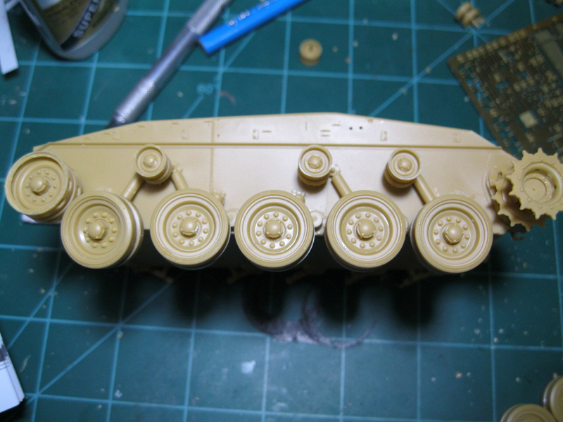
Overall, this is a really nice, very detailed kit. Some items, such as the workable suspension and recoiling gun, were essentially worthless to me because of a lack of stability and durability of the parts. I don't know if it was worth it to have the rear engine deck broken down into so many separate components, but it did go together. Fit was generally very good, with any fit issues resolved by sanding or trimming-nothing was undersized. The locator pins on the road wheels allow significant wobbling and some sort of jig will be required to get the wheels to sit right. The individual link tracks snapped together easily and required only slight cleanup at the three sprue attachment points.
Lack of indication on some of the etch as to where to make bends was a little frustrating, as were some of the vague points in the instructions. The instructions don't flow well, with sub assemblies being built and then set aside instead of going into their specific larger assemblies. The plastic is very thin, and some parts are delicate, but there is a nice, scale appearance to the thickness as well.
The build was not an easy process, and I was certainly glad when I completed the tank, but I am quite satisfied with the details in the results. I wanted to take a picture with the running gear and tracks in place, but they were too loose to set in place temporarily.
If you are looking to build a model of the M24, and if you have some patience and skill, this is certainly a good kit, and I have no regrets over getting this instead of the Italeri kit. It comes with plenty of extras, including stowage, jerry cans, the milk jug, and the crew figures, as well as showing some basic interior details.
I purchased the kit online at Lucky Model for $49.99 before shipping, as it was the best price I found. Shop around online or your LHS and look for the best deal you can.


Comments