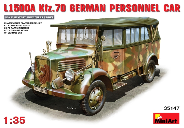
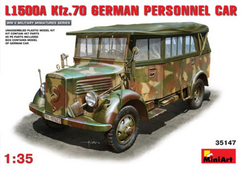
MiniArt 35147 1/35 scale L1500A Kfz. 70 German Personnel Car
Introduction
In 1938, in an effort to standardize German Army personnel cars (PKW) and military truck (LKW) manufacturing to ease mass production, the Wehrmacht Ordnance Office (Waffenamt) embarked upon the Schell Plan. Until this time, most Wehrmacht PKW and LKW were procured from the civilian market and consisted of more than 100 vehicle types from over 20 manufacturing firms. These myriad of vehicles were unsuited for the rigors of military service and created a nightmare for the maintenance crews as well as logistics for spare parts.
One of the Schell Plan designs by the Mercedes-Benz firm for the new 1.5 ton LKW class was the 1500 series. Two types were put in production, a 2-whhel drive L1500 S-typ (4x2) and the 4-wheel drive L1500 A-typ (4x4). Both were based on the 1500 light truck chassis but production concentrated on the A-typ for military service, which the subject of this MiniArt kit and review. The L1500A was a very sturdy and rugged vehicle with superior off-road capabilities. The chassis incorporated a ladder type frame with two longitudinal semi-elliptical leaf springs and a rigid banjo type axle at the rear. The front end was rather sophisticated, incorporating a swinging arm independent suspension with two longitudinal semi-elliptical leaf springs. The gearbox and auxiliary transfer case, as well as the front drive case were all bolted to the crankcase. The L1500A was powered by the Daimler-Benz M-159, a 2.6 liter (2594 cm³) in-line 6 cylinder petrol engine creating 60 bhp.
Weighing in at 5,269 lbs (2,390 kg) the Mercedes-Benz L1500A was officially classified as a light truck (LKW) in the 1.5 ton class. The chassis was used for many specialized vehicles, each with its own body type, including radio vans, cargo trucks, weapons carriers, light prime movers as well as a heavy type personnel car. The Heavy Personnel Car version, given the motor vehicle (Kraftfahrzeug) number 70, or Kfz. 70 for short, was an open bodied car with a folding canvas top, had seating for seven, (including driver) and was often used as a command car. About 4900 were manufactured between 1941 and 1943 and was well liked by the troops.
Mercedes-Benz L1500 A-Typ Specifications
Manufactured: ................1941-1943
Produced: ........................4,900
Body: ...............................open Kfz. 1 type (Kübelwagen) with seating for seven (driver 6)
Engine: ............................inline 2,594cc (2.6 liter) six-cylinder four-stroke
Length: ............................4930 mm
Width: .............................2050 mm
Height: ............................2225 mm
Wheelbase: .....................3000mm
Track Front axle: .............1575 mm
Rear Track: ......................1634 mm
Transmission: ..................4 speed forward & reverse, w/transfer case for engaging 4-wheel drive.
Suspension: .....................Leaf springs (quarter-elliptical)
Brakes: .............................hydraulic drum type on all wheels
Drive: ...............................4x4
Weight: ............................2390 kg (maximum 4080 kg on the road)
Max speed: ......................84 km/h
Fuel tank: .........................70 liter capacity
Consumption: ...................19 L/100km (field 30 L/100km)
Range: ...............................370 km (field 230 km) 4x4, 1.5-ton w/60hp 6-cyl gasoline engine
Contents
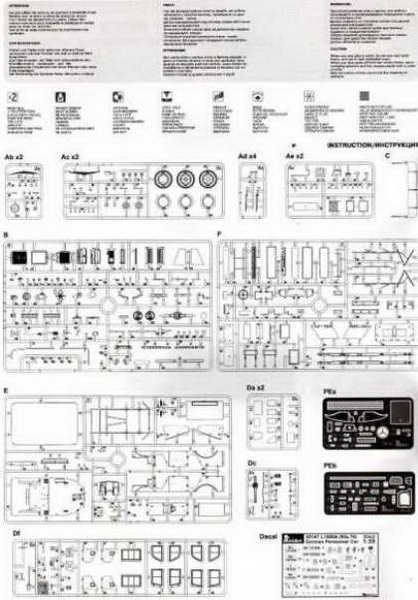
The kit is packaged in the typical box with lid. The parts sprues are all in a single cellophane bag and are molded in a light-medium gray styrene. This is a completely newly tooled kit with 467 plastic and 86 photo-etched parts. Heres the contents breakdown:
15 sprues in light-medium gray styrene
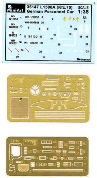
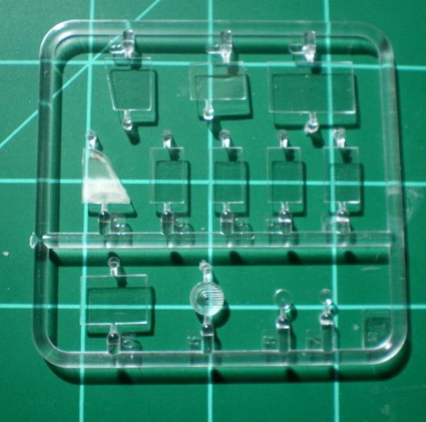
2 clear styrene sprues (windows, headlight lenses etc.)
2 Photo-Etch frets
1 decal sheet
12 page booklet style assembly manual printed on high quality glossy paper
Quality of molding is rather good with very little flash, smallish sprue gates, very few ejector pin marks with most being hidden after assembly, and, of course, the usual seam lines that appear on any styrene kit. Only the usual clean-up of parts will be required and there are many tiny parts that will require care when removing from the sprue and during clean-up. The overall quality is really top notch compared to many other Eastern European manufacturers, and compares well with the top model companies.
Construction
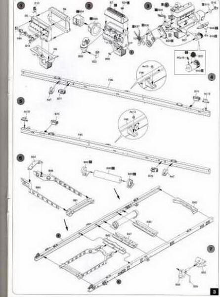
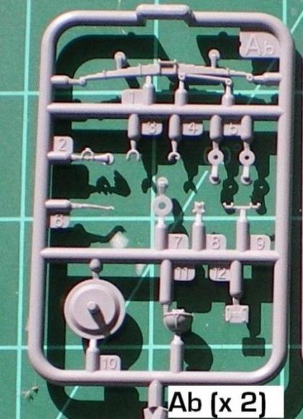
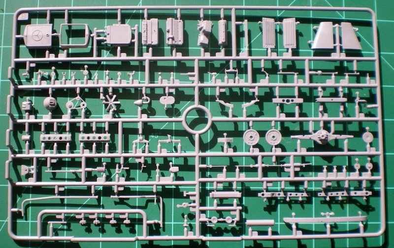
The first four assembly stepsdeal with the engine and transmission sub-assembly. The engine and transmission consists of approximately 30 parts and is quite detailed. The engine block is in 2 halves with separate parts for the oil pan with oil cooler, exhaust manifold, valve cover, fuel pump, carburetor, ignition distributor, intake manifold, water pump, timing chain cover, a 3-part starter, radiator hose, harmonic balancer/alternator/water pump pulleys with belt and a radiator fan. To this assembly is attached the transmission, gearbox, motor mounts and U-joints for the driveshaft. Theres also a few other parts I cant identify as well. Suffice it to say, very little will be needed to make this engine hum, such as ignition wires, fuel lines and other ancillary wires.
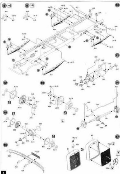
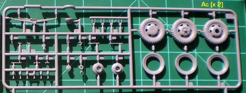
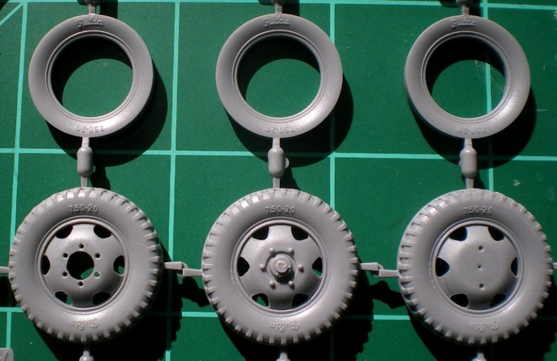
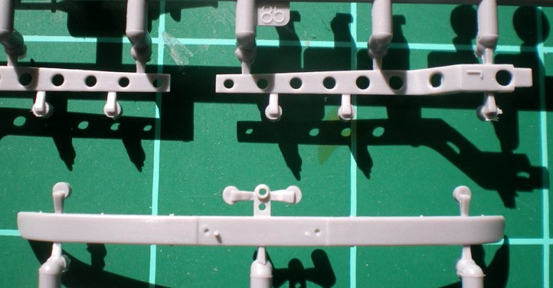
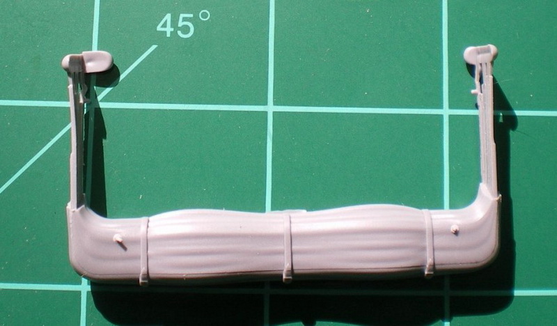
Steps 5-10entail the chassis frame assembly. The ladder frame is constructed from two long U-shaped beams with the ladder cross members in between and several other small detail parts added such as muffler and exhaust pipe. Care will be needed to make sure this is assembled straight and true, as proper fitting of the body will depend on it. To the frame is added the four quarter-elliptical leaf springs with mounting brackets and engine mounting frame. Steps 11-17 are each a separate sub-assembly for different components that include a 10-part drive transfer case, two 7-part front drum brake/steering assemblies, rear transaxle/drum brakes assembly and two optional radiator assemblies. The first option is a single part radiator/hood enclosure with a molded on 3-dimensional (convex) Mercedes emblem and topped off with a radiator cap and photo-etched hood ornament. The other option has the radiator and hood enclosure as separate parts with a photo-etched (flat) Mercedes emblem and crank starter guide hole. This option omits the radiator cap and photo-etched hood ornament, but I think this is in error and should be added as per the first option. I think the second option provides better detail definition even with the flattened PE emblem and you could also just leave off the PE radiator emblem as Ive noticed it missing in many period photos. Check your references. In steps 18-22 all of the above sub-assemblies are attached to the frame as well as the wheels. Each wheel is a 4-part assembly with an inner part trapped between the outer rim/tire part and the inner rim part. The wheels are designed to turn after assembly. To this is added a photo-etched inner rim. The wheel rims appear to be of the more common type and the tires are embossed with the German Fulda name brand and the tire size numbers 7.50-20. Its difficult to determine from period photos if the tire tread pattern and size is accurate, but I have found a few photos that appear very similar to the kit tires. With the addition of the wheels engine/transmission assembly and front bumper with photo-etched number plate, the chassis construction is complete.
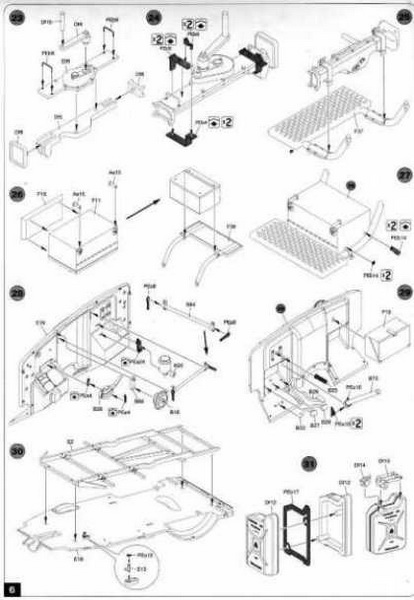
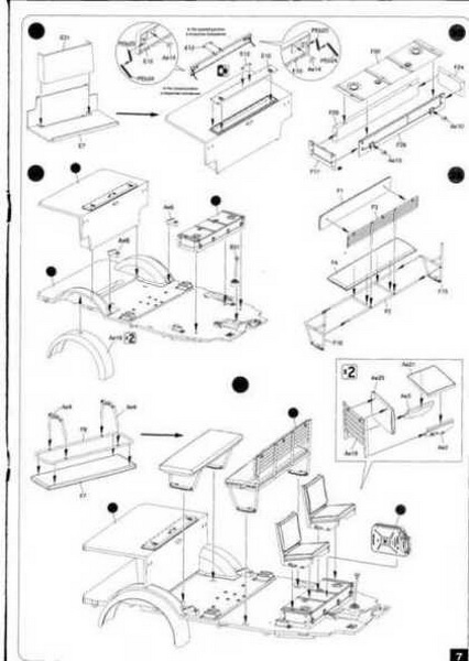
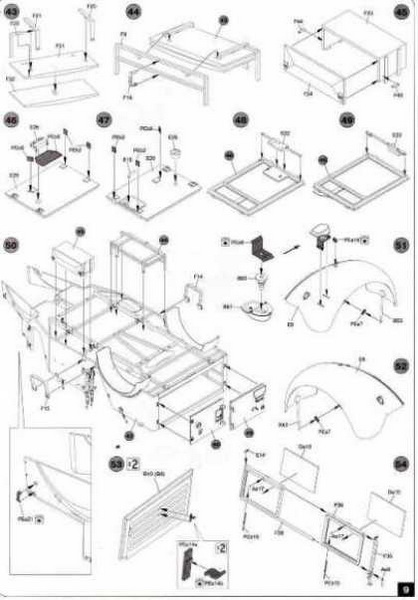
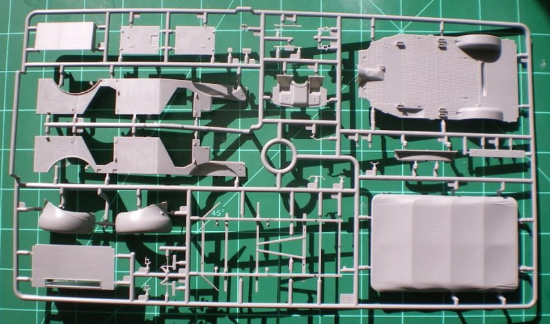
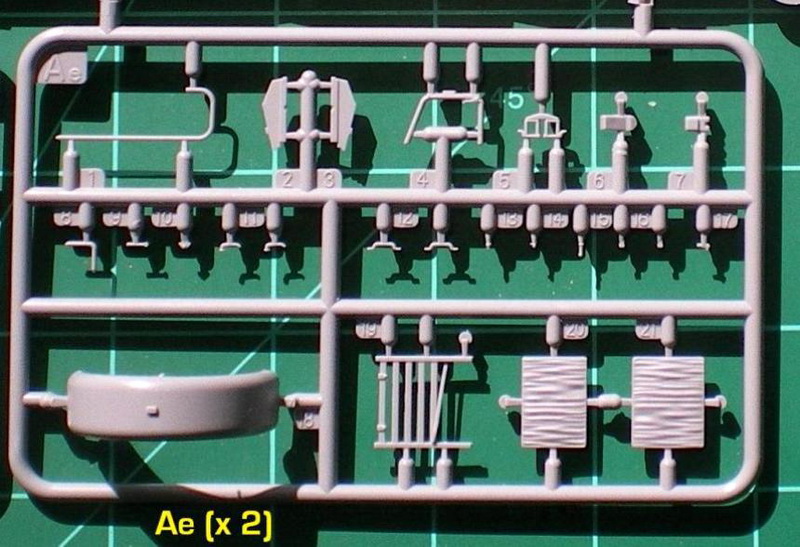
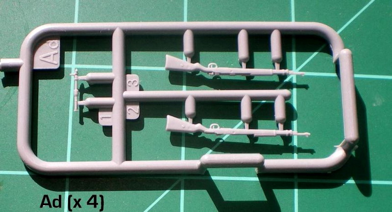
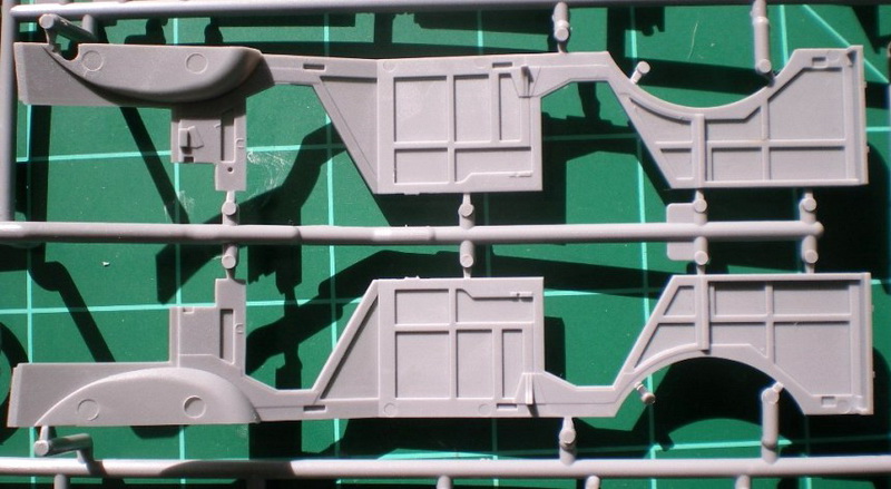
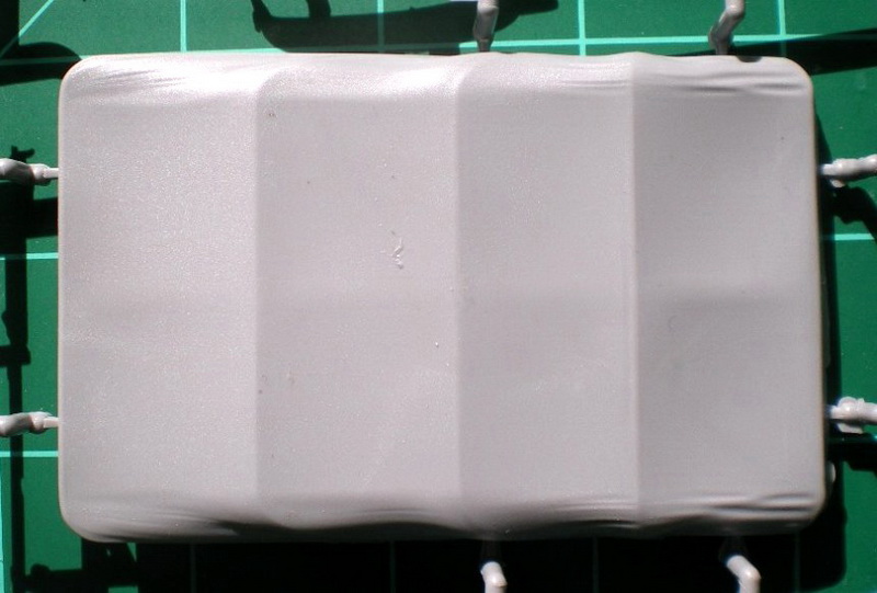
Moving to steps 23-36; there are several sub-assemblies and sub-sub-assemblies to construct the floor body of the vehicle. Some of these assemblies are complicated and it seems like theres a separate part for just about everything. Steps 23 & 24 have you assemble the vehicles jack, consisting of 6 plastic parts and no less than 8 photo-etched parts representing grab handles and mounting brackets with wing-nuts. The jack mounts to one of the 5-part grated running boards and a 4-part tool box is mounted to the opposite side running board. Both of which are added to the chassis in step 64. Steps 28/29 add all the parts to the firewall. The engine side of the firewall consists of 12 parts, 4 of which are photo-etched and include a horn and some kind of linkage arm. There are a few other parts that I cant identify but will lend well to the under the hood look. The passenger side of the firewall consists of 7 parts and includes steering shaft with two photo-etched mounting brackets and separate parts each for the accelerator, brake and clutch pedals. Step 30 mates the floor panel with the floor sub-frame. The floor is well detailed with a non-slip surface and the rifle rack footings molded in place. Make a note that there are a few ejector pin marks on the underside of the floor that will need attention before adding the sub-frame. Step 31 has you assemble a 5-part 20 liter jerrycan with photo-etched weld insert and a separate cap and handle. The jerrycan is also nicely embossed with the proper Kraftstoff 20Lmarking and fits between the two front seats in step 36. Next is the interior rear deck assembly that has an option for an open or closed access panel. I think this may be the storage area for the window panels when they are not in use. For the opened panel option, there is a 2-part photo-etched hinge assembly for each of the two hinges. This, along with a 6-part fuel tank, a 4-wheel drive engagement lever and the rear fenders are added to the floor assembly. Also added at this point (step 36) are the two 4-part front seats over the fuel tank, multi-part rear bench seats with backrest as well as several other small parts. The seat cushions all have molded in wrinkles and to my eye looks a bit exaggerated. Im not sure about the accuracy of this as my references are lacking in this area. Steps 37-50 continue with the body and interior assembly. Step 37 has you assemble another bottle type hydraulic jack that mounts on the interior transmission hump in front of the gear shift/manual brake levers. This consists of 3 styrene parts with a photo-etched mounting bracket and a 5-part photo-etched strap. Also for the interior are 4 single rifle racks and two double rifle racks. Make a note that in step 42, the two 2-part double-rifle racks that attach to the side panels have the part numbers reversed in the instructions. These rifle racks may be a bit over scale but look rather good for this medium. Strangely, four of the 8 rifles provided in the kit have separate bolt parts, while the other four have molded on bolts. Other interior items include a spare wheel/tire, gear shift and parking brake levers and a few other small bits. To all this is added the body side panels with molded on wood sub-frame to which an axe with photo-etched brackets and clips, some tiny grab handles and the above mentioned double rifle racks. Steps 43-49 are more sub-assemblies that attach to the main assembly in step 50. These include a 7-part rack (steps 43/44) and a 4-part tool/stowage box (step 45), both of which mount on the underside of the vehicle. Steps 46-49 are the 2 rear panel trunk access doors that include tiny photo-etched hinge details, tail-light/reflector, rear Notek Convoy light with photo-etched mounting bracket as well as interior locking mechanism if you want to show the trunk access door(s) open. Step 60 adds the above sub-assemblies to the main assembly as well as two rear crew compartment access steps and a photo etched mounting bracket for the pick-axe (added later) on the passenger side engine panel.
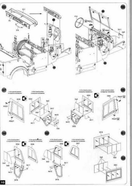
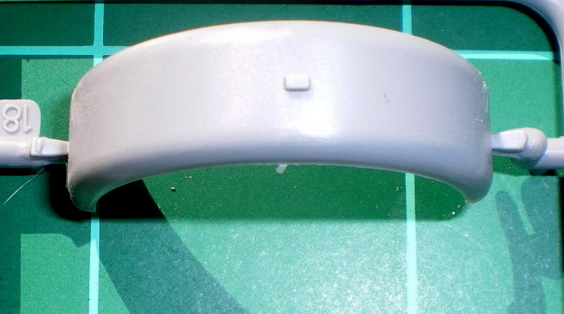
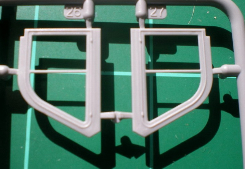
Moving on to steps 51-54, the front fenders a windscreen is assembled. Each fender gets a width indicator pole with photo-etched mounting bracket. These might be best left off until final assembly to prevent breakage. Also added to the port (drivers) side fender is a 2-part hooded Notek light with a 2-part photo-etched mounting bracket. The windscreen assembly consists of eleven parts. These include some very tiny plastic locking handles, separate glazing (glass) parts and 2 photo-etched wiper blades with tiny plastic wiper blade arms. The parts are very delicate and care will be needed to remove the parts from the sprues and in assembling them. It also appears that the drivers side windscreen, provided as separate parts, can also be modeled in the swung open position. The instructions dont show this option, but it looks to be easy enough to do. Squeezed in between the above steps is step 53, which adds a 2-part photo-etched clip to the interior side of each of the louvered side engine access panels. These are stowage clips for the braces that hold the engine access panels in the upright position when accessing the engine compartment.
Moving to steps 55/56, the firewall and windscreen sub-assemblies are added to the main assembly. The dashboard is also added which consists of two main parts and a separate grab handle. The dashboard has nicely embossed dials and knobs but sadly there are no decals provided. Im sure Archer Transfers will have a set soon. The final additions to step 56 are two photo-etched brackets on top of the dashboard and the nicely molded steering wheel.
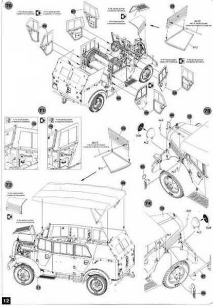
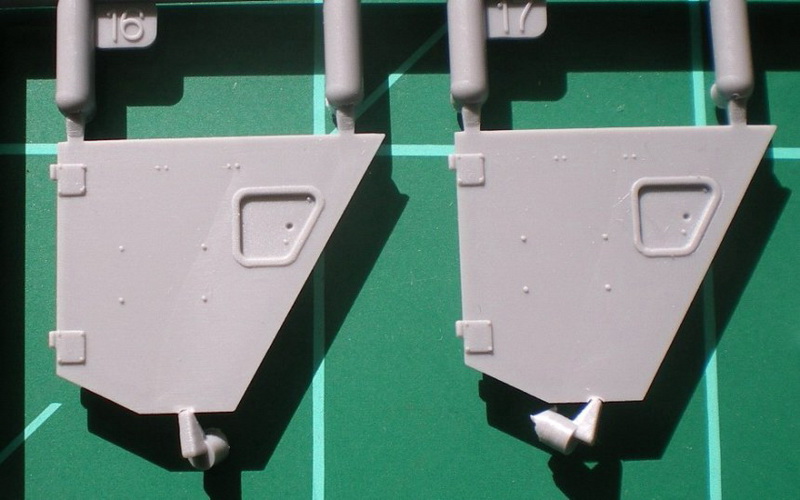
Steps 57-60 are the four passenger door panel assembles. Each door panel has an alternative canvas top glazing enclosure panel for optional open or closed position. This was rather confusing at first as I thought the option was open/closed windows. But looking carefully at the parts and instructions the parts are for the option of open/closed doors. When the doors are shut, the canvas top part sits flush with the rest of the canvas top, but when opened, the canvas on the door would flop out. So, the parts represent one of the two options. Two of the door panels also each have two photo-etched parts added for the open option. Each door also has separate glass panels for the windows. They are respectably thin but I believe on the prototype these glass panels were made of a plastic material and the kit parts may look too much like glass. It would be easy enough to replace these glass panels with scratched cellophane material if so desired. Also added to each door are separate interior and exterior door handles. Steps 61-62 show two 4-part assemblies for the canvas/glass side panels that go between the passenger doors. These two panels along with the other side and rear canvas panels, also with separate glass panels and the front fender sub-assemblies are added to the main body assembly. In this step you are also given the option of adding the folded down canvas top that is provided as a single part. I have seen in reference photos the side and door canvas top panels in place with the main top folded, but you can also leave off the side panels as well. The canvas in all of the above parts is rather well rendered for plastic kit parts and should look very convincing after assembly.
Moving on to step 64, the main body assembly is mated with the frame assembly. Also added at this point is the radiator assembly from step 17, with a brace that connects it to the firewall, the side running boards from steps 25 and 27 and finally a nice little photo-etched chain for the rear trailer hitch. In steps 65 & 67 are assembled two 3-part turn indicators with brackets and rearview mirrors. The passenger side indicator also includes the siren and both are added in the final assembly steps. Steps 67 & 68 have you assemble the axe and shovel, each a single part with photo-etched brackets, clasps. Step 69 is the canvas cover top sub-assembly and consists of a well rendered canvas and a very delicate frame. The frame is nicely done and very delicate. Care will be needed removing it from the sprue. Steps 70-74 are the final assembly. Here you add the door panels, open or closed as per your build, two 2-part hood panels with the closed option or with an additional hood brace part for the opened option. Also added are the canvas top parts, two headlights with clear lenses, shovel, axe and the above mention turn indicators/mirrors.
Marking and Painting Options
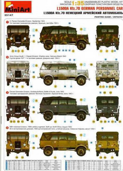
The front cover of the instruction manual shows four marking and painting options. At the bottom of the page is a paint chart for Vallejo, Testors, Humbrol, Revell, Mr. Color and Life Color paints. The four painting and marking options provided for in the kit are: 3. Panzer-Grenadier Division, September 1944. This option shows a tactical marking of a motorized signals platoon with heavily mottled 3-tone camouflage scheme.
Army Group South, 1. Panzer-Division, Kharkov area, February 1943. This option shows SS license plates, a motorized rifle company tactical sign and the divisional sign for the 1. SS-Panzer-Grenadier-Division Leibstandarte Adolf Hitler so is not of the 1. Pz.Div. This vehicle shows a heavily warn whitewash over the panzer grey base.
Panzer-Grenadier-Division Großdeutschland, Battle of Kursk, June 1943. In overall German grey, this option has the iconic Stahlhelm unit badge insignia with the tactical sign of a motorized rifle company.
90th Motorized-Division, 190th Artillery Regiment staff car, North Africa August 1942. Painted in the typical Afrika Mustard color, this option sports the tactical marking of an artillery staff vehicle.
Instructions
The instructions provided are in booklet form with stapled binding printed on A4 size, glossy type paper with 12 pages. As mention above, the cover shows the marking and painting options. The first page shows the parts sprue layout. Pages 3-12 show the assembly instructions in CAD isometric, exploded view format divided into 74 assembly steps. The instructions are quite clear, placement of parts are vague in only a few areas that I found and shouldnt cause any problems for experienced modelers.
Conclusion
This is really well detailed kit and unfortunately is not for the beginner as there are some very tiny parts. There are also no plastic options for any of the photo-etched parts, and some of these are extremely small and may be frustrating even for experienced modelers. Other than that, I can find no faults with the model. It would have been nice to have some decals for the instrument gauges. This really isnt a fault as the dashboard will be difficult to see if you opt for the enclosed canvas top. But if you want to show off the interior, Im sure an aftermarket decal company like Archer will produce some soon. MiniArt has been a good up and comer in the 1/35 scale market and even though is still using older molding technology they know how best to utilize it and producing some very nice kits of interesting subjects. This kit, the Mercedes-Bens L1500A, earns two thumbs up from me.
References
Trucks of the Wehrmacht by R.Frank; Schiffer Military History; 1994
German Personnel Cars in Wartime by R. Frank; Schiffer Military History; 1989
dr. Hans Georg Mayer-Stein, Mercedes PKW 1935-1945, Waffen Arsenal Special Issue No. S-59, 1993.
dr. Hans Georg Mayer-Stein, Mercedes LKW 1935-1945, Waffen Arsenal Special issue No. S-62, 2001.
W. Spielberger, Militärfahrzeug: German Softskinned Vehicles of WW2, Aero Publishing, 1970.
SUMMARY
Highs: Multimedia construction with very fine details. A very nivley rendered canvas top. Lows: No decals for the instrument gauges. No plastic replacement parts for the PE for those modelers who dont like PE. Some very tiny PE parts.Verdict: As detail goes, it doesnt get much better than this. I would have liked decals for the instrument gauges but Ill be happy to spend a few $ extra for aftermarket decals. Ive built a few softskins in my time, and this has to be the best one Ive seen.
Our Thanks to MiniArt! This item was provided by them for the purpose of having it reviewed on this KitMaker Network site. If you would like your kit, book, or product reviewed, please contact us.
About Cpt. C. Sosebee, USA (Ret (csosus) FROM: TEXAS, UNITED STATES
Back into modeling after almost 26 years in the US Army as enlisted and as an officer. Over those years, I've collected quite a library of military history books, vehicle references and quite a few kits too. I only build 1/35 WWII, any nationality. Currently my modeling skills aren't really that ...
like the look of this as something different. I need something to tow my Pak 38, I know the chassis could be sued but would that have a different body or could this incarnation be used (I guess in a general retreat, if it was available it was used)?
Hi Rob,
According to my research for this vehicle and review, the L1500A was issued as a prime mover for light guns, such as the 2cm FlaK 30/38, 3.7cm FlaK 38/43 and possibly even the 3.7cm PaK 35/36. Generally though it was used as a personnel carrier and a heavy staff/command car. I haven't seen any photos of L1500A's, by any of the three manufacturers (Steyr, Horch or Mercedes-Benz), towing a 5cm PaK 38. I believe the 5cm PaK's generally used half-tracked prime movers such as the Sd.Kfz. 10, or even the RSO. But I suppose, in a pinch, the L1500A could have been used. MiniArt has also releasded the cargo version of the L1500A and you might consider this one as well. It's on my wish list.
See here: LINK
I hope this answers you questions.
Cory
WOW and already they have brought out a 2x4 AND 4x4 truck version of this vehicle WITH a Fire Truck and Trailer on the way.
We are really going to get tired of building this same chassis before this run is over!
FANTASTIC!


Comments