Introduction
MPK Modellbau is a Swiss company relatively new to the production of complete plastic kits, though its designer is a model master maker of many years experience. At the time of writing there are around 15 kits in their MK72 (i.e. 1/72 scale) range, and 2012 saw the release of the Panzerjäger Marder II, the subject of this review.
Early in the war in the East, the T34 proved that German anti-tank weapons were inadequate; having already successfully proved the concept by mounting captured 7.62cm Russian guns on to 38(t) and Pz.Kpfw II chassis, most of the production of the Pz.Kpfw II was switched, in June 1942, to producing an open topped mounting on the Ausf F chassis for the 7.5cm PaK40/2. Production continued for about a year before being being completely switched to producing the Wespe, following which, further Marder II vehicles were produced by converting existing Pz.Kpfw II tanks. The vehicle apparently served on all fronts, and some are known to have still been in use into 1945.
What you get
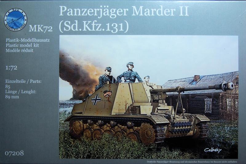
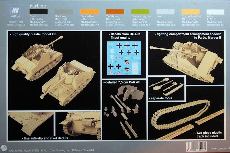
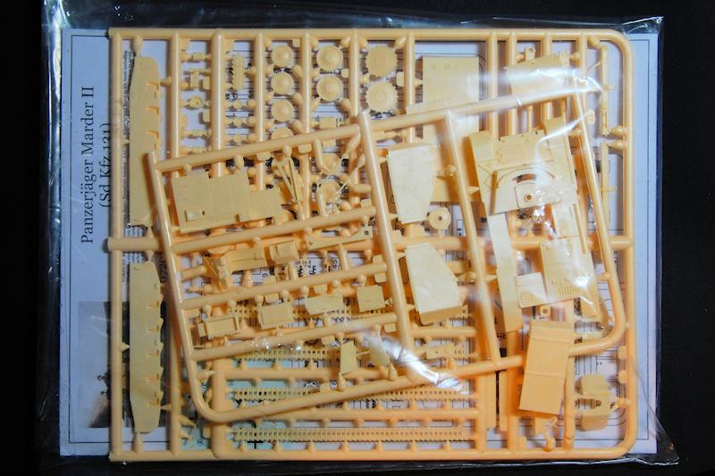
Packaging is in an end-opening box with the contents contained within a sealed polythene bag. The slightly fuzzy box art is, I think, a digital painting combining the 3D CAD model for the kit with the well-known posed propaganda photograph of the vehicle named Kohlenklau (Coal Thief) from 1943, with the addition of a building and a column of smoke in the distance. It is of course the same vehicle which Tamiya depicted with their 1/35 scale version. The reverse features some quite useful shots of what seems to be the CAD model again.
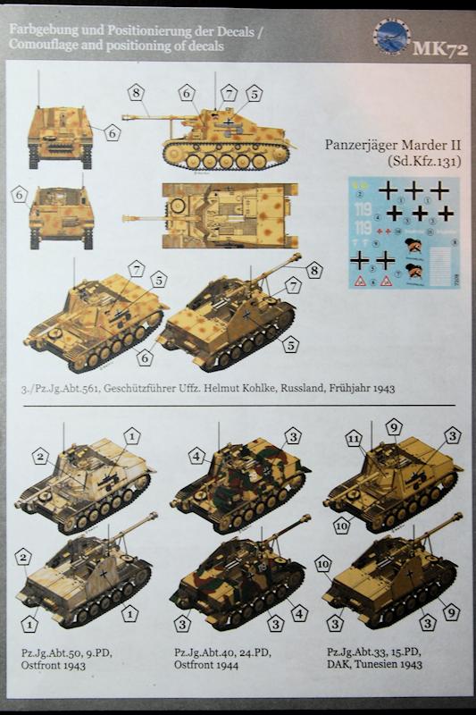
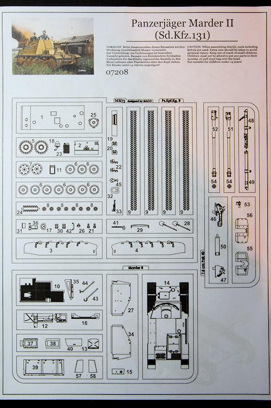
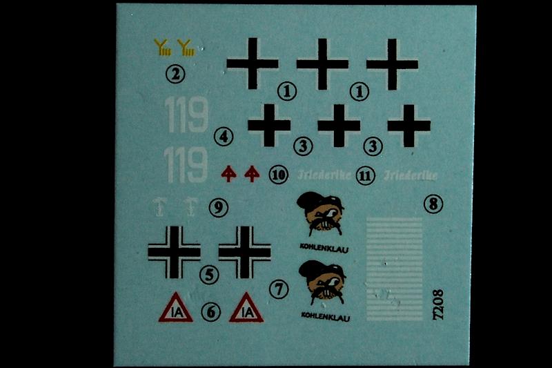
The instructions are a six-sided fold-out with a numbered parts diagram of the three sprues, and there is a separate full colour sheet illustrating the four distinctly different finishes that can be achieved by using the supplied decals: three from the East - our Kohlenklau of course, in dark yellow with red-brown spots, a white-washed 9th Panzer Division machine, a 24th Panzer example in three-colour patches, and an Afrika Korps vehicle operating in Tunisia, 1943.
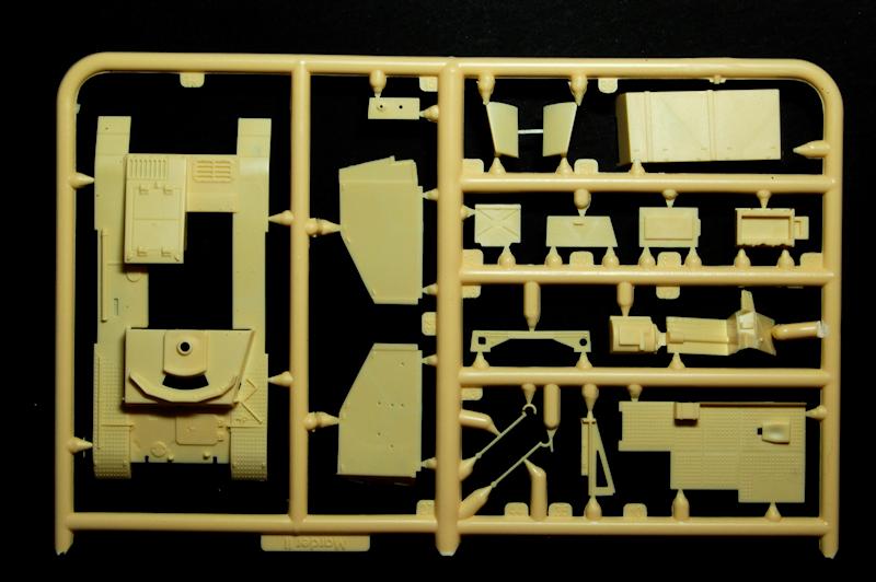
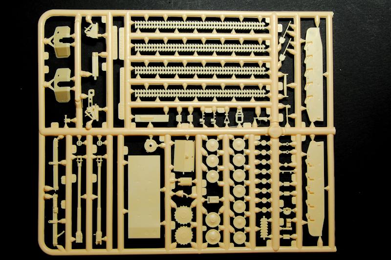
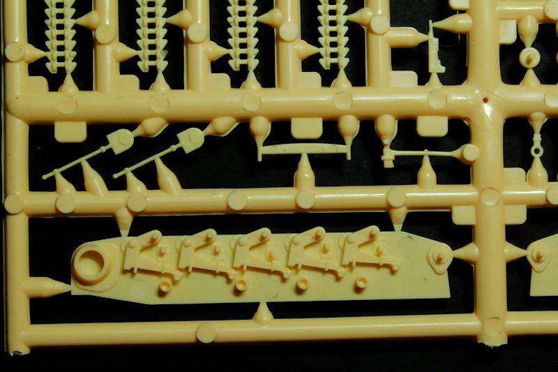
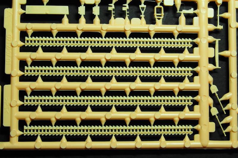
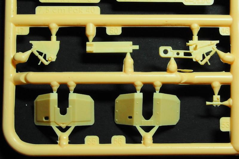
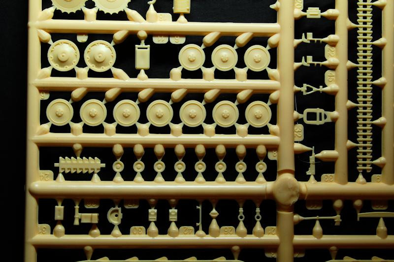
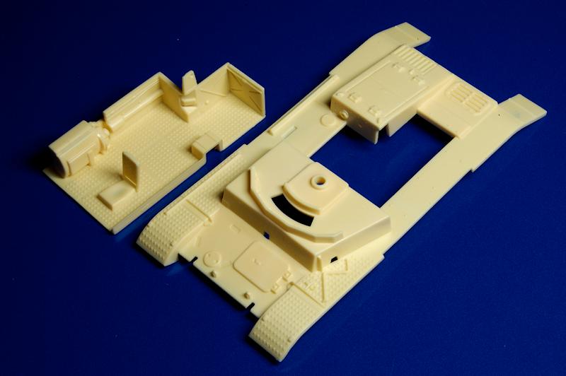
The three sprues are broken down in such a way to lead us to expect more from these moulds: wheels, tracks (moulded in two long sections per side), tools and the hull base and sides are on a sprue labelled Pz.Kpf.Kg.II; the sprue with the fighting compartment interior and the hull top and sides is named Marder II, while the gun parts are on the PaK40 sprue.
The pale cream coloured plastic moulding is very crisp, with detail sharply produced and rather fine sprue attachment points. Mould seam lines are minimal, although there are a number of pin marks which need to be dealt with, as we will see. There appeared to be some blackish release oil visible in places. The parts are moulded notably thin, which means that items like the armoured sides and the gun shield are produced with what looks like authentic scale thickness, so there is none of the tapered edges that manufacturers sometimes use to obtain a scale looking thickness to such plates, nor is there any necessity to reduce the thickness of any of the plates by sanding or filing. This fine moulding is also used to achieve the appearance of scale dimensions of some of the smaller parts as well, resulting in some VERY thin components which need careful handling (inevitably, more on that later
) The moulding is actually so unusual that it is quite striking: the flat plates are literally translucent, and the finesse of the components is contrasted by the odd thickness of the sprues themselves.
Construction
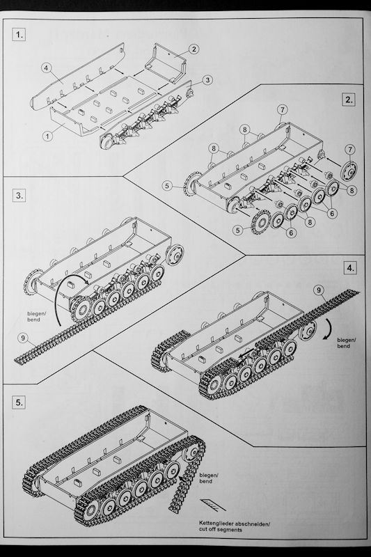
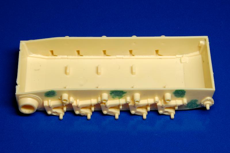
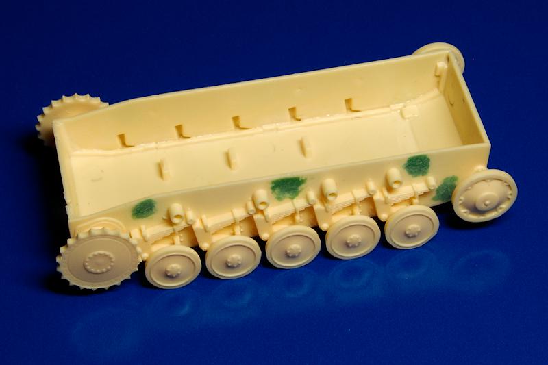
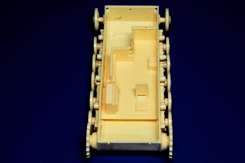
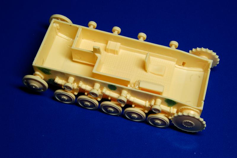
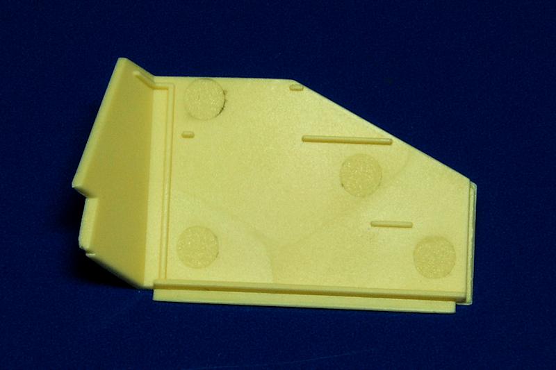
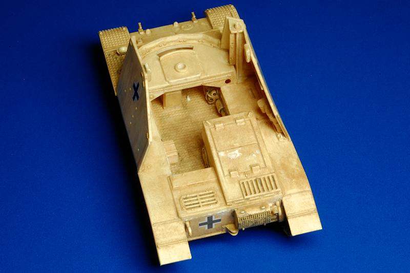
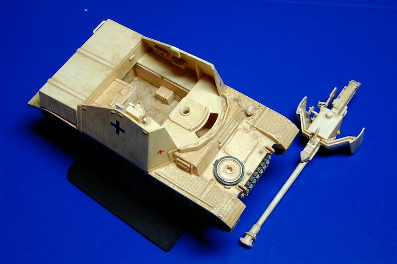
We start off building up the hull by attaching the floor / glacis plate to the sides and the rear plate; in photo 20 observe the nicely aligned fit of the parts, but also the four pin depressions on each side that needed filling with putty. The front end of the floor plate bends a little (the thin plastic) so, with no locating guides on the sides, the top of it needs to positioned in line with the top of the hull sides while the cement does its work. Visible in photo 22 are the hull bottom details, but also the sink marks that sit under the fighting compartment floor mounting pegs.
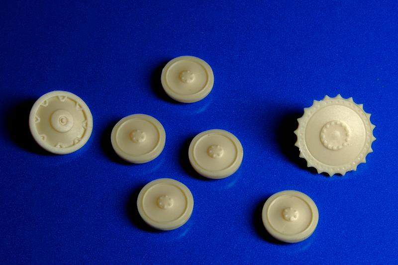
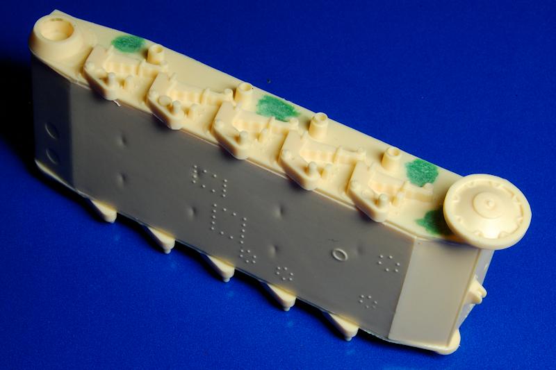
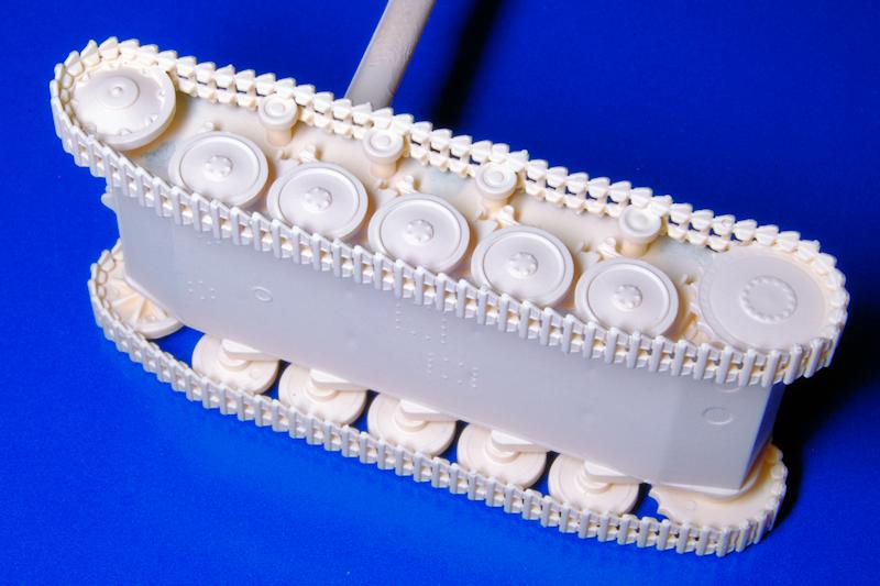
At stage 2 all the wheels come off the sprues and on to the hull; Pz.Kpfw II models are something of a joy with their all-one-piece wheels! A projecting piece of moulding obstructed the wheels at the second station on each side, but was easily removed, after which the road wheels all line up quite easily (photo 23) along with the sprocket; I found I had to slightly shorten the cap on the back of the idler in order to sit it slightly closer to the hull so that it aligned with the other wheels, and some similar adjustment to the return roller mounts was necessary.
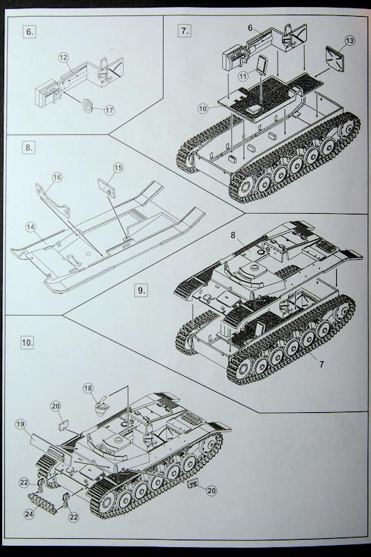
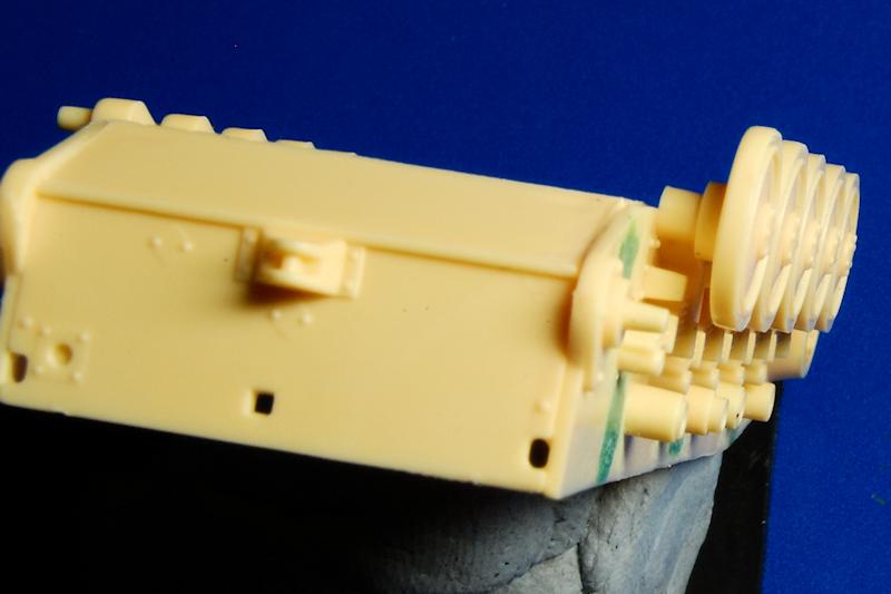
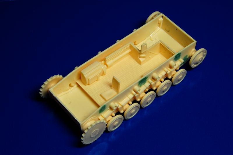
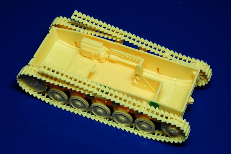
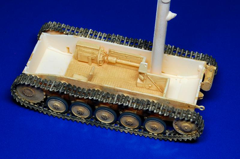
Rather than fitting the tracks, as per the instructions, I then moved to the fighting compartment floor, stages 6 and 7; the right hand side wall includes the transmission housing, to which an end cover is attached prior to it being mounted on to the floor along with the drivers seat and the rear bulkhead (photo 25). This assembly then slots, nice and true, in to the hull bottom (photo 26 and 27).
Its at this point that you really need to make a decision on how youre going to assemble and paint the model. The issue seems to be that the interior compartment needs to be painted and the tracks need to be attached, both, probably, before the hull top is attached. Well consider this again later
but for now I ignored the instructions which show the top going on, and went back to the tracks in stages 3, 4 and 5.
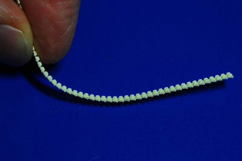
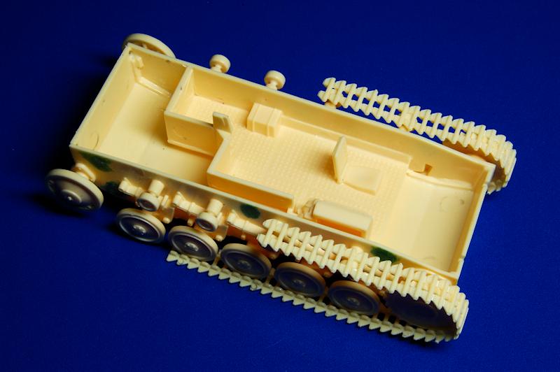
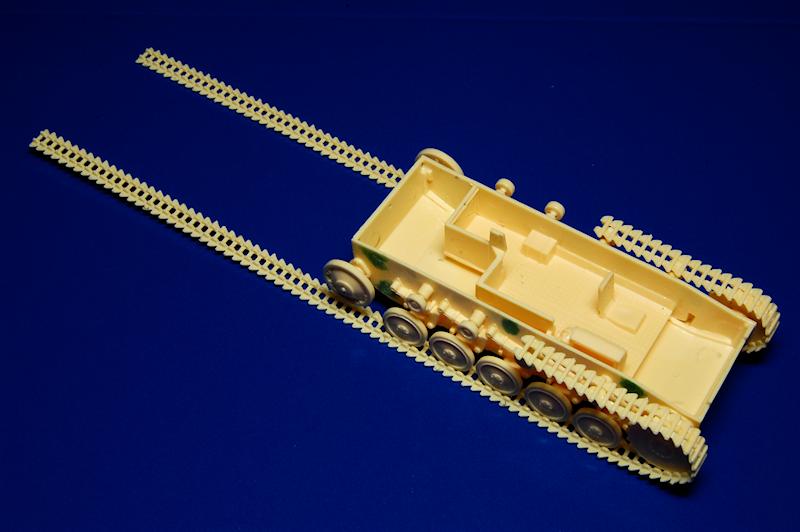
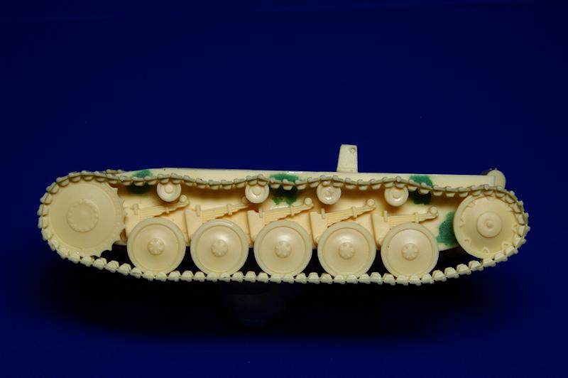
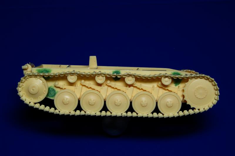
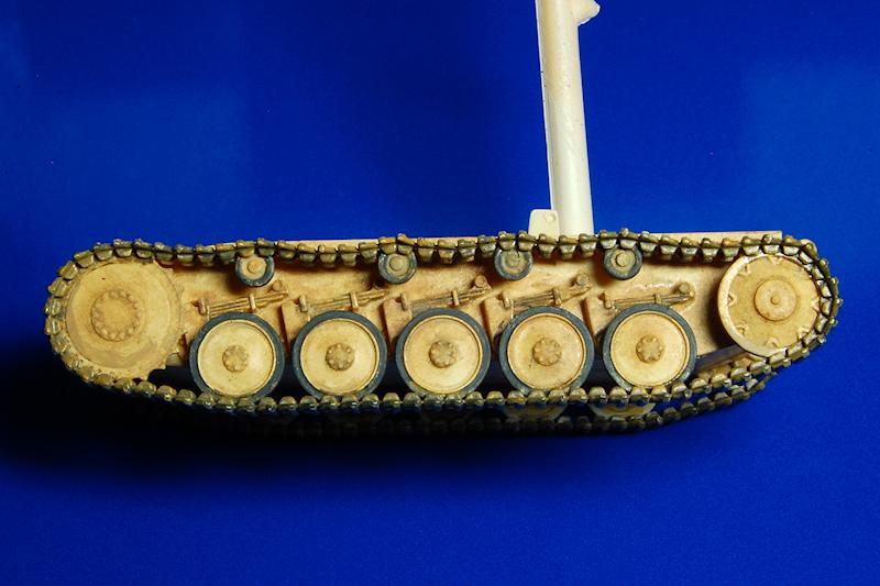
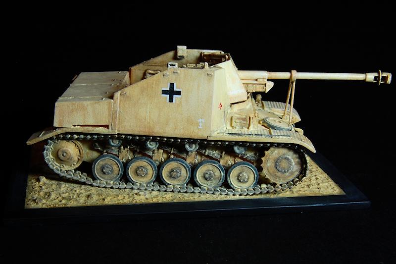
The tracks come in two lengths for each side, considerably longer than is required, so theres plenty of spare. The detail is somewhat simplified in that the tread has a rather heavier, blockier appearance when compared to the real thing. In photo 28, however, you can see how the very finely moulded plastic allows the necessary bend to be achieved to enable the tracks to wrap around the wheels. Its possible to manipulate the tracks to get them sitting very closely around the sprocket and idler, and to introduce sag by cementing them slightly around the return rollers. I started with the front part of both sides and allowed the cement to set overnight before proceeding with the rear length. In order to obtain an exact join between two links it was necessary to test the fitting first and to introduce a certain amount of track sag (photo 33 and 34); obviously you want to avoid either a gap or an overlap with at the joins.
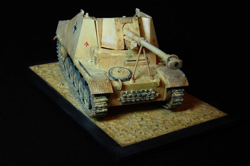
Note that all of the box art (including the box top painting) and the instructions show the tracks on upside down. The chevron shape of the track link should be pointing up like an arrow when viewed from the front.
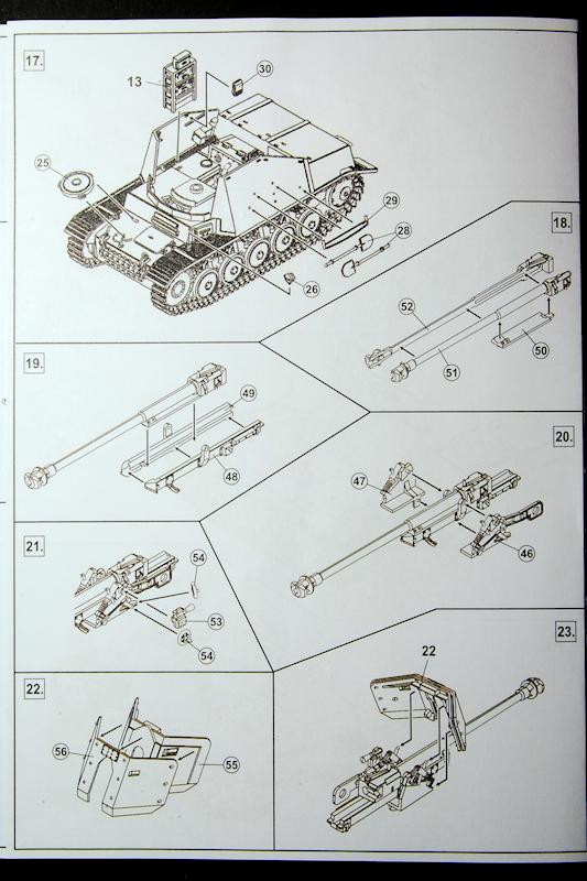
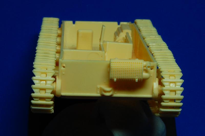
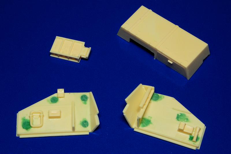
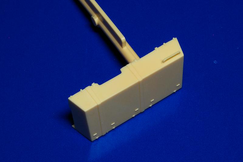
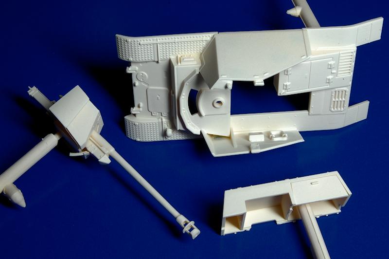
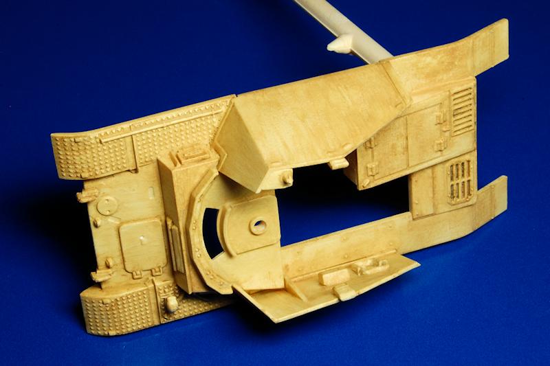
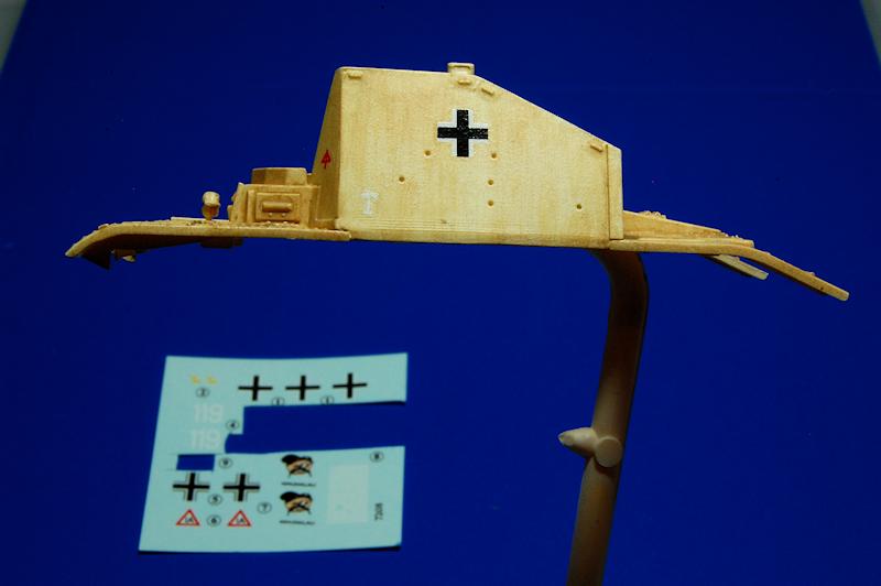
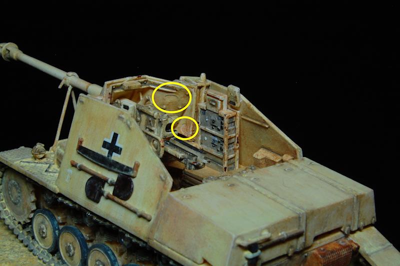
I then proceeded with building up the hull top (stages 11-15) and the gun(18-24), alternating between them to cemented parts to set. In photo 36 we can see the four big circular marks on the inside of the side armour that really need to be filled, see photos 37 and 48, along with the big radio stack and the (presumably) ammunition storage compartments that sit over the engine deck.
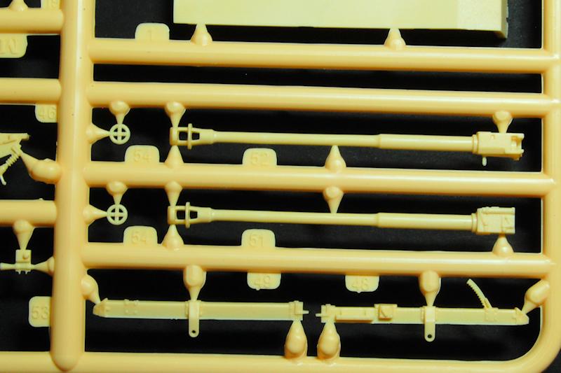
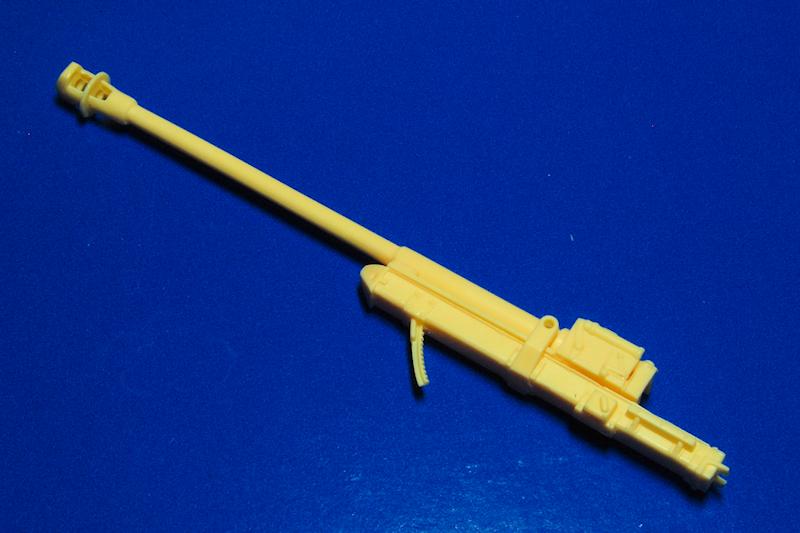
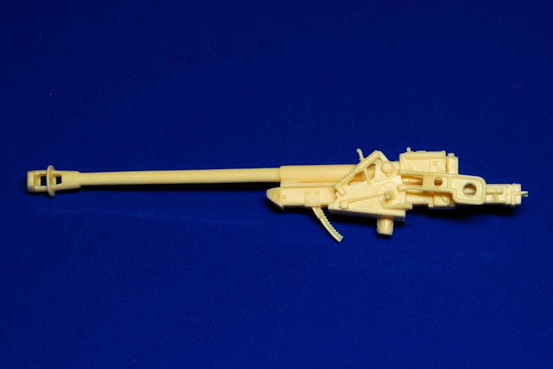
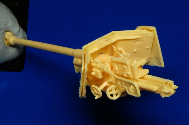
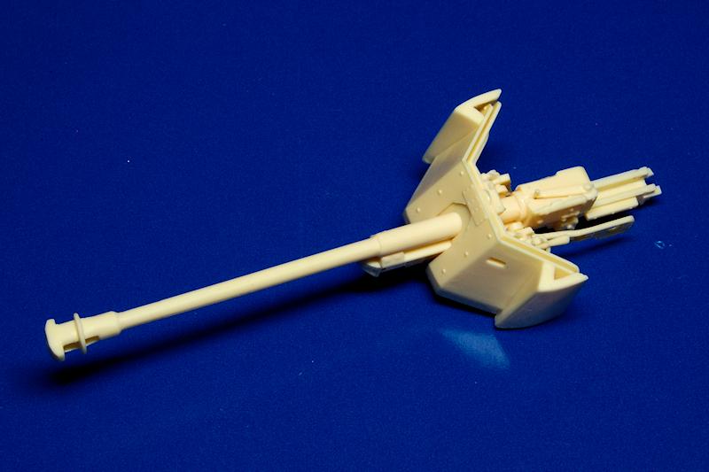
The gun barrel, including the muzzle brake, is in two halves, thankfully with no locating pins provided (which normally only serve to misalign the halves) and just needed the mating surfaces to be smoothed down for a good fit. Notice in photo 38, the very fine breech lever handle that projects from the top of the block, and again, in photo 39, the delicacy of the moulding for the gun cradle; be very careful with these parts! I lost that handle at some point. The double skin gun shield is nicely rendered, again thanks to the thin moulding, but observe once more circular ejector marks evident on the inner face of the shield and also on the inside of the outer shield that the standard PaK 40 shield slots into (photo 42). The hand wheels are well depicted, and notice too the gun sight; needless to say this is all quite fiddly building, and care, a steady hand and some decent tweezers are needed.
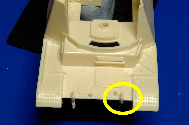
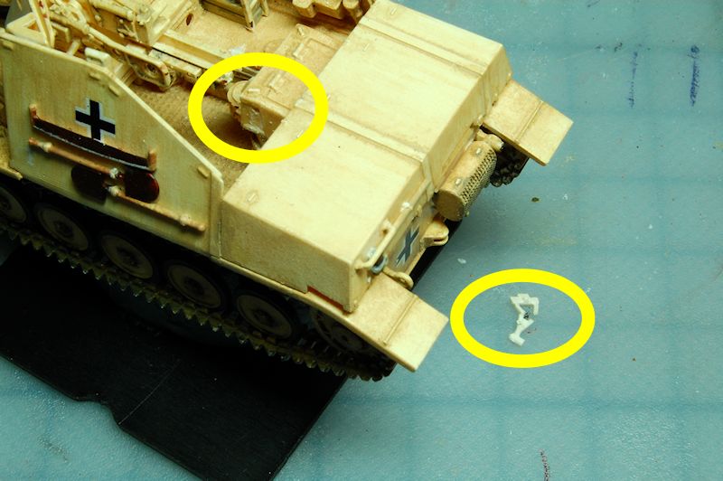
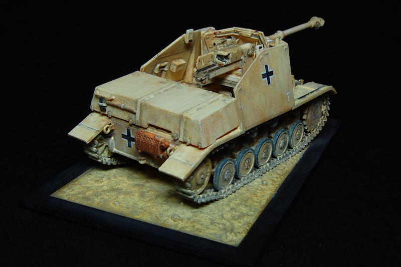
Moving to the hull top, from stage 10, we can see in photos 44 and 45 another breakage: parts 22 are the combined tow hooks and spare track mounting brackets; I managed to snap off, then lose, the bottom of one of them. In the end, having studied photographs, I came to the conclusion that not all vehicles had this style of spare track bracket, some appearing to have the spare links mounted lower down on the glacis, with the two tow hooks being completely separate; therefore I cut the other one off to match. (For evidence, see Bundesarchiv photos Bild 101I-686-0084-30 and 31, although note that this vehicle also has two headlamps.)
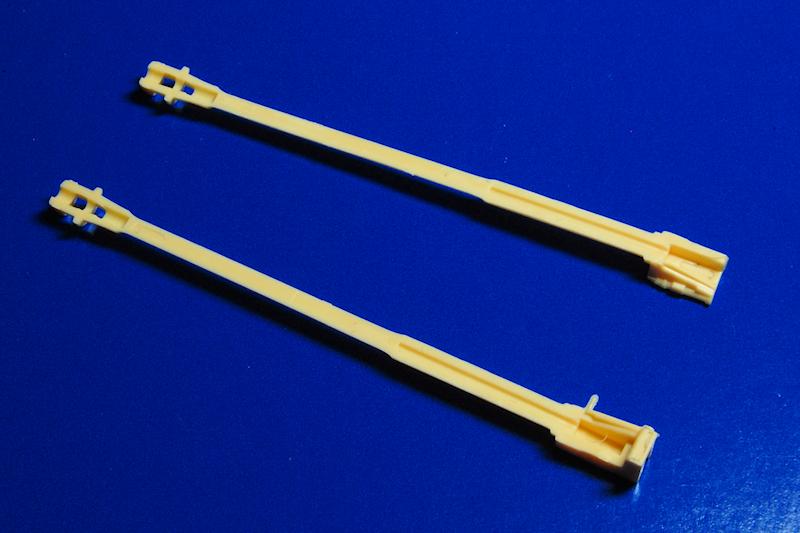
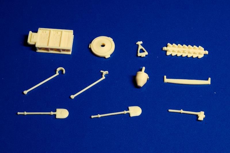
Many of the small detail components added at stages 10, 16 and 17 were prepared in one go for painting and later assembly: photo 46 shows the separate shovels, saw and axe, as well as the radio rack and the breech and barrel gun stays; these gun stays, once again, are
extremely delicate and I managed to break one of the two barrel stays
and the breech clamp completely in half. The individual tools are a welcome feature, though the shovels have a rather flat, spatula-like appearance that can be reshaped with some careful filing, and the top of the saw can be thinned down.
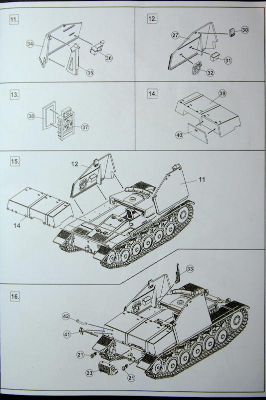
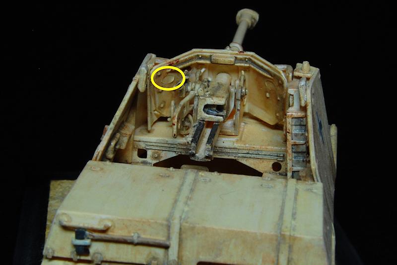
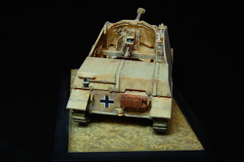
Stage 11 omits an illustration of the attachment of the side periscope, part 30, though it is shown for the other side in stage 12; both have small locating pins on the back of the armour plate which are best removed to allow a closer fit. The storage compartment that fits on the back needs the attachment of a door, and this fitted so perfectly that I actually deliberately fitted it slightly skewed to give a more separate appearance.
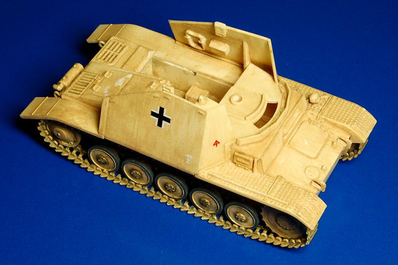
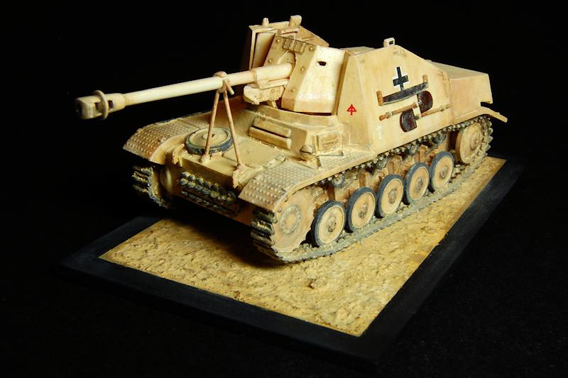
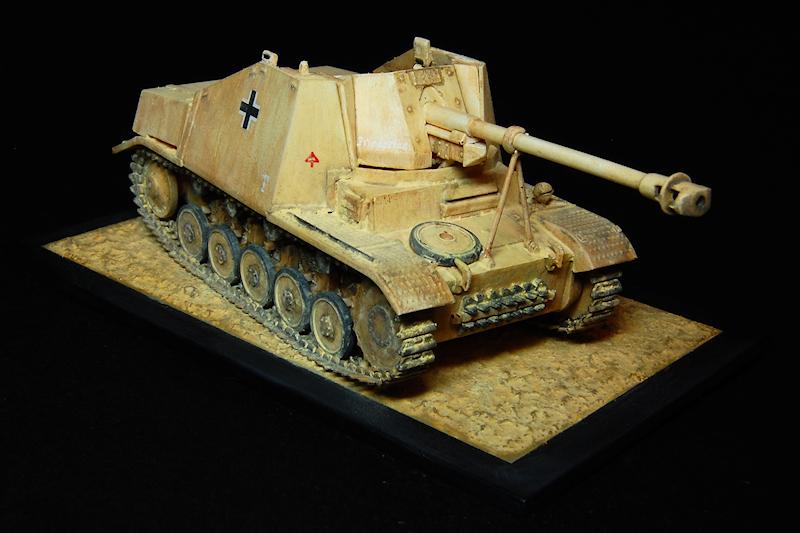
Photos 49 and 50 show the main components sprayed in white car primer; this was followed with a very thin brush applied coat of Liquitex Unbleached Titanium, followed by an uneven filter of Yellow Oxide (photos 51 and 52). The decals were then applied straight on to this painted surface using Micro Sol and Set, and they all sat perfectly thin and flat without any glossy underlay being necessary. Further discolouration and shadowing was added with a Burnt Umber / Yellow Oxide mix.
Now the hull top was attached; this is where painting beforehand results in some rework being necessary at the joins on the nose and rear. I didnt succeed in getting a perfect fit at these points, and with paint on and the quite delicate tracks fitted, didnt want to do too much fiddling around to force it. There was a bit of overhang of the hull top at the nose that necessitated some filing to get a flat appearance, and this, and a slight gap at the rear, were filled with Winsor and Newton acrylic paste, which adheres to a painted surface and was tinted with paint to blend in.
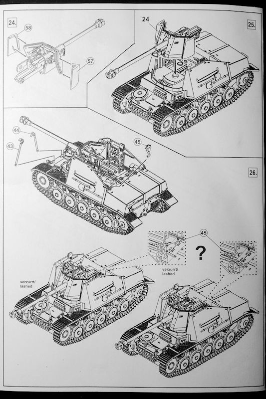
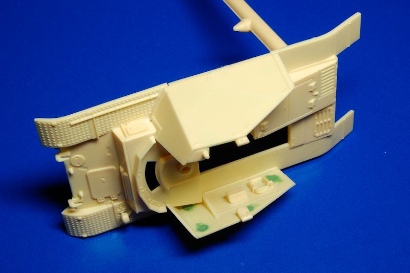
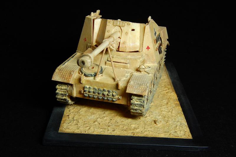
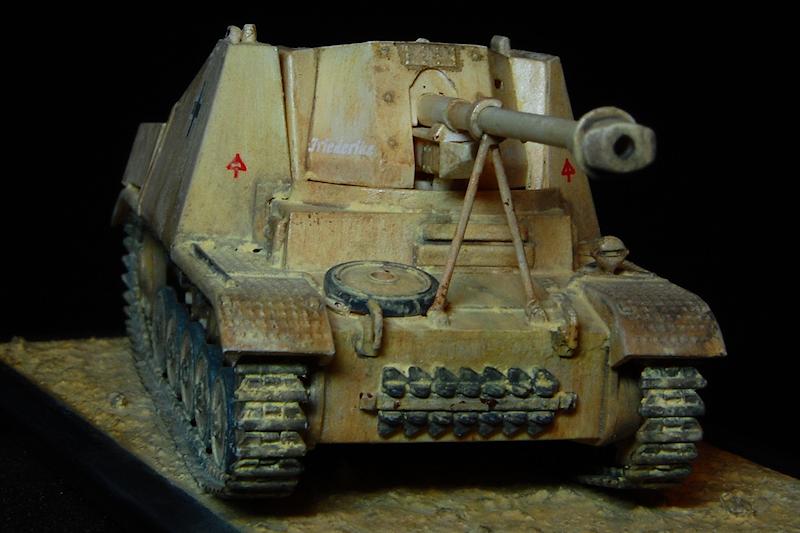
Photo 57 takes us to stage 25, the mounting of the gun, which I didnt find too easy. Two problems: first the mounting hole was too small, so this was enlarged, but then the whole gun still seemed to sit too high, so that the top of the gun shield was well above the side armour. The raised collar around the mounting hole was removed completely, and the crescent shaped ridge in front of it, and the rectangular surface of the gun base, were reduced, so that the gun sat 1 to 2mm lower down. The side armour also had to be prised slightly apart with open pliers in order to allow the gun shields to fit through
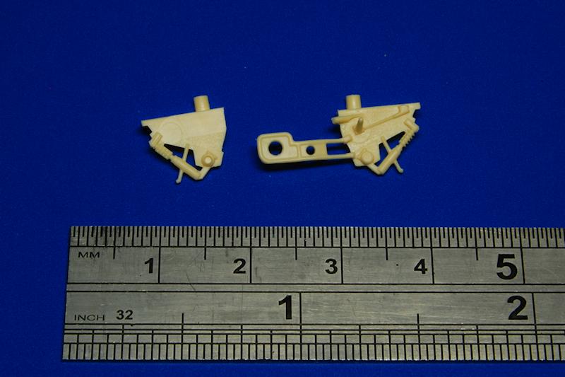
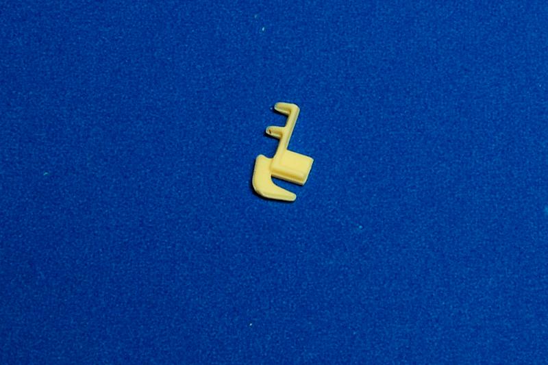
The final stage, 26, shows the options for fitting the barrel clamps and the breech clamp in either lashed (travel) position, or unlashed (firing) configuration. If intending to fit them lashed, I would suggest actually fitting the breech clamp to the gun when building the gun in stage 23 or 24; positioning it with the gun in place requires aligning the clamp exactly onto the end of the breech slider and into the hole in the fighting compartment, and it is quite awkward, to say the least. Of course the clamps on the barrel end also need to be fitted onto the hinge points on the nose and then onto the barrel itself, and getting this more exposed end right is critical to the overall appearance of the finished model. Photo 58 shows what happened to my breech clamp: snapped in two, and the empty mounting hole. I started scratching a new one from rod, but then accidentally melted that replacement with glue, so it remains as an omission.
Conclusion
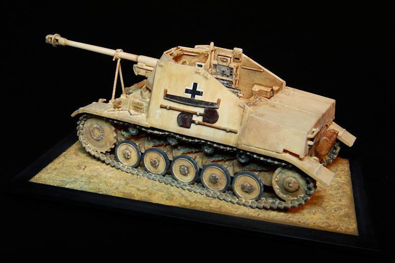
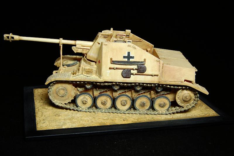
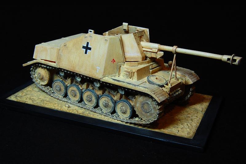
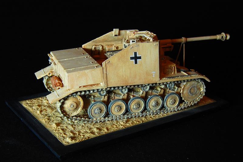
So, this was a very enjoyable kit to make, and as the photos show, I was really drawn into wanting to finish it in terms of painting and weathering. The fit of parts is very good, and the separately moulded tools and the finesse of many of the details result in a model that is both pleasing in appearance and a pleasure to build due to the relative lack of compromises that have been made. While the moulding techniques may not be at quite the technical level of recent Dragon kits, there are still some impressive parts, such as the exhaust muffler, the hull top and some of the gun details, and it is certainly the case that sprue attachment points are mostly rather fine, and considerately positioned, so that removal and preparation of components is relatively easy. The model generally therefore seems to have been well thought out and designed. The instructions are adequately clear, with only one or two errors, the painting guide good, and the decals are of fine quality.
On the negative side is the quite large number of ejector type circular marks that occur in visible places. The part of the kit that shows the most compromise is perhaps the tracks, which are somewhat simplified, although I have to say that I thought the method of producing the tracks worked well otherwise, in that they were easy enough to handle, shape and fit, and a nice track sagging appearance was easily achieved; on the finished model I think they look good. Theres a slight issue with the way the armoured sides meet the track guards in that they come down to the bottom of the track guard, and break the run of the track guard into three sections; photos show that the armour plates stop at the top of the track guard, with a visible join, and the track guards should have the appearance of being one unbroken strip. It is of course something that could be fixed by those that are bothered by this kind of thing.
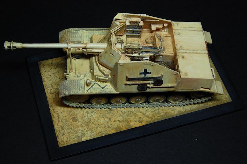
As discussed, the thinness of some of the parts can create some awkward moments in construction, while at the same time providing a pleasing quality. The overall delicacy of the model is one of the reasons I chose to mount it immediately on to a base, as I couldnt face any more handling of it!
I am certainly looking forward to building another kit from this same manufacturer. Note that it is possible to purchase directly from the companys website:
MPK Modellbau
References
Bundesarchiv Picture Database (just type marder into the Search box).
Encyclopedia of German Tanks of World War Two by Hilary Doyle and Peter Chamberlain, Technical Editor
Thomas L Jentz (to whom we all owe so much knowledge.) (A&AP)


Comments