Introduction
The Pz.Kpfw.III is an interesting staging post in armour development of the late thirties and early forties; originally conceived as a tank-killing tank in 1936, and first fitted with a 37mm gun, as it was the standard anti-tank gun in use at the time, its designers far-sightedly gave it a big enough turret ring to accommodate a 50mm gun. Thus it was able to be up-gunned, first with a 50mm L/42, and then with the longer L/60, keeping it sufficiently competitive to continue in production into 1943.
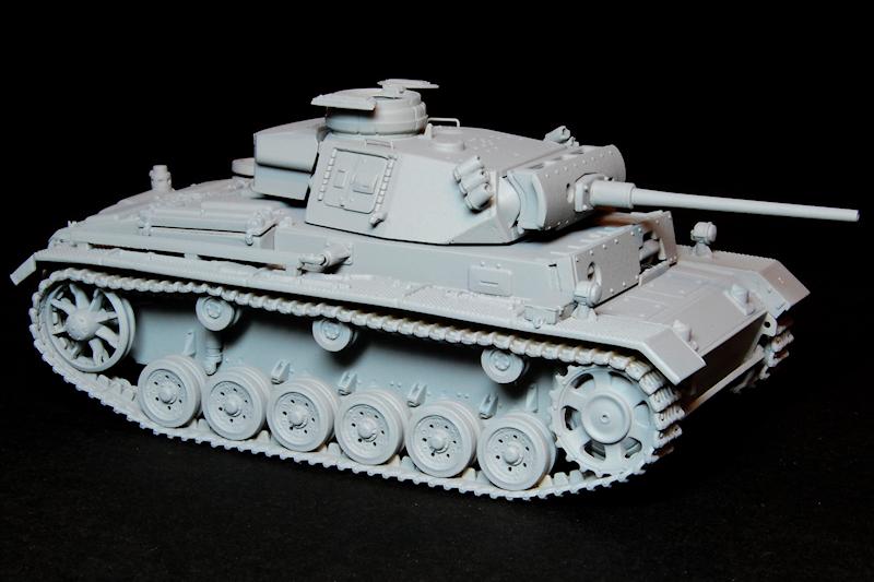
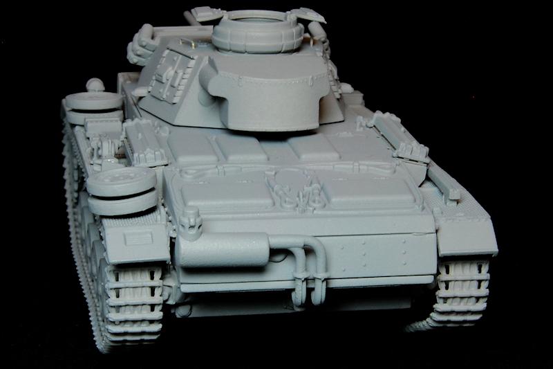
Dragon released four 1/72 Pz.Kpfw.III variants in 2012, the Late Production L, the bare DAK N, the M, and more recently the N with side skirts. Our subject here is the Ausf.M, similar to the L with its L/60 gun, and while some differences, the elimination of the hull escape hatches and the hull side vision ports, related to production efficiency, there was also the introduction of features prompted by conditions on the Eastern Front: the ability to wade to a depth of 1.5 metres provided by a revised exhaust system and water tight seals, and a facility for the transfer of hot engine coolant from tank to tank to facilitate cold engine starts.
What you get
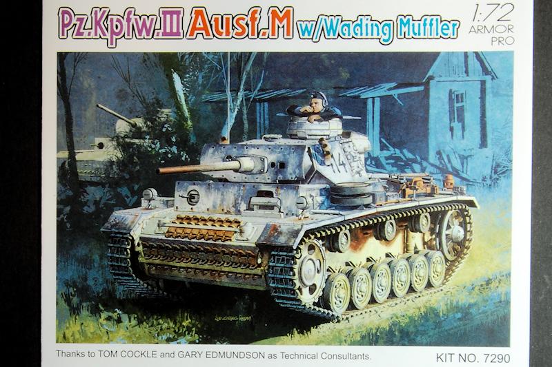
Packed in a two part carton with cover art identical to the kits 1/35 scale big brother, depicting a worn whitewash over grey tank trundling past a dilapidated peasant house somewhere in the east, a pensive commander sitting low in the turret, along with the dim light, gives the scene a sombre air.
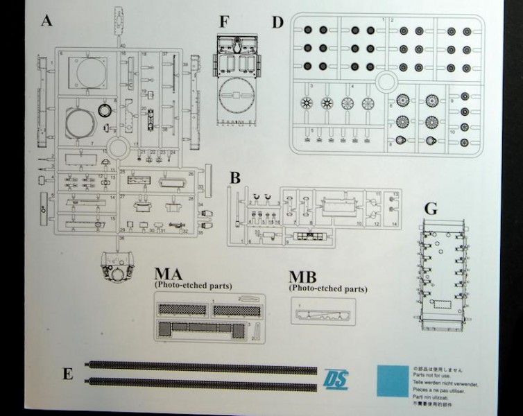
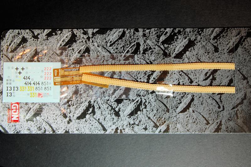
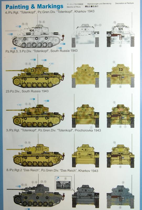
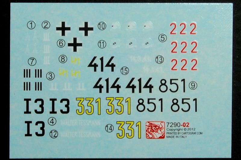
Instructions are the usual glossy Dragon style, with everything happening on one side of the sheet; the front shows the sprue layout, while the back gives three way views of five finishing options: three dark yellow variants, a grey and a winter white example, all dated 1943. Decals for these schemes make up any of three Totenkopf tanks, a Das Reich tank or one from 23 Panzer Division.
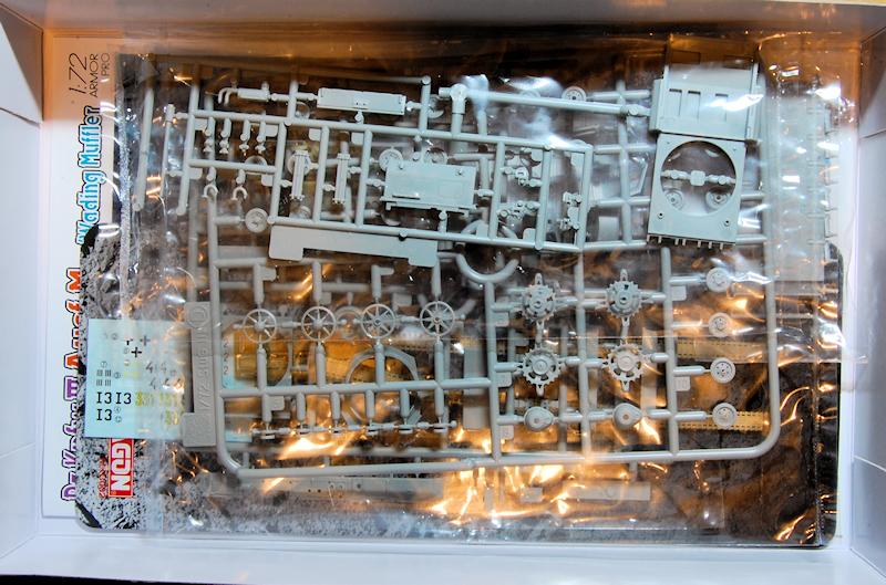
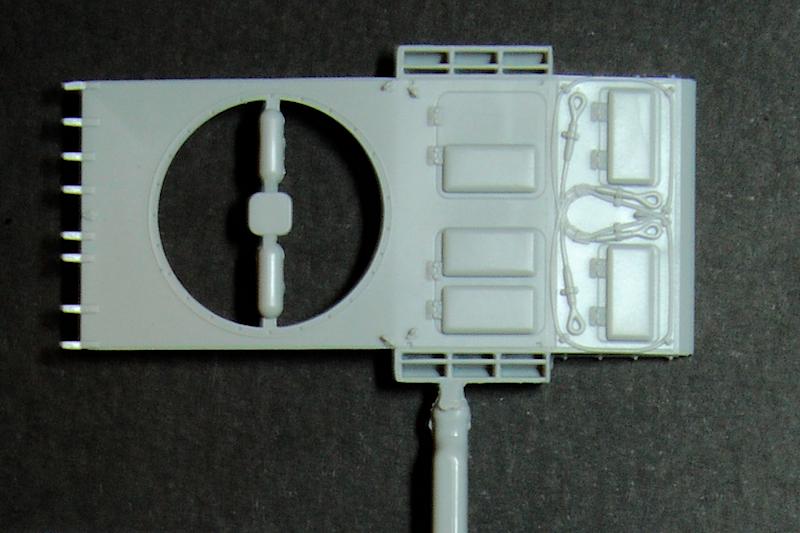
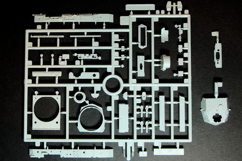
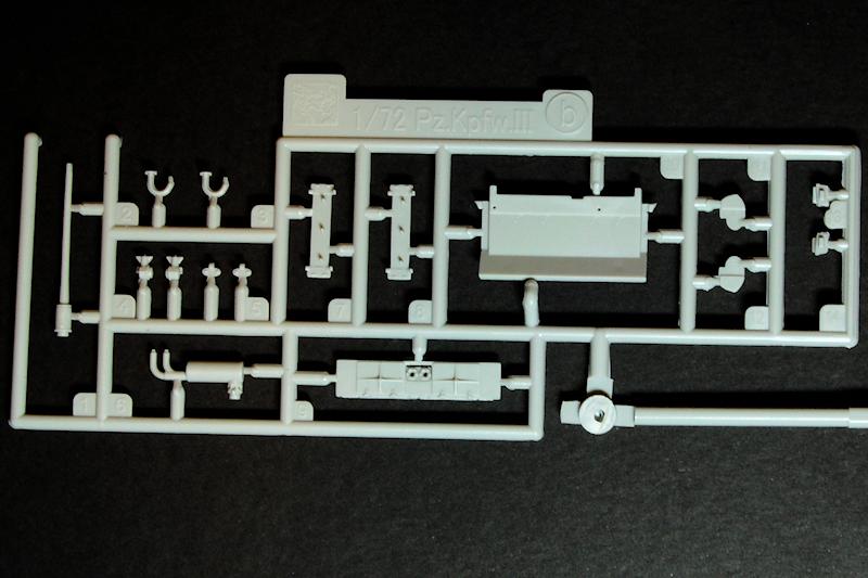
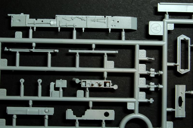
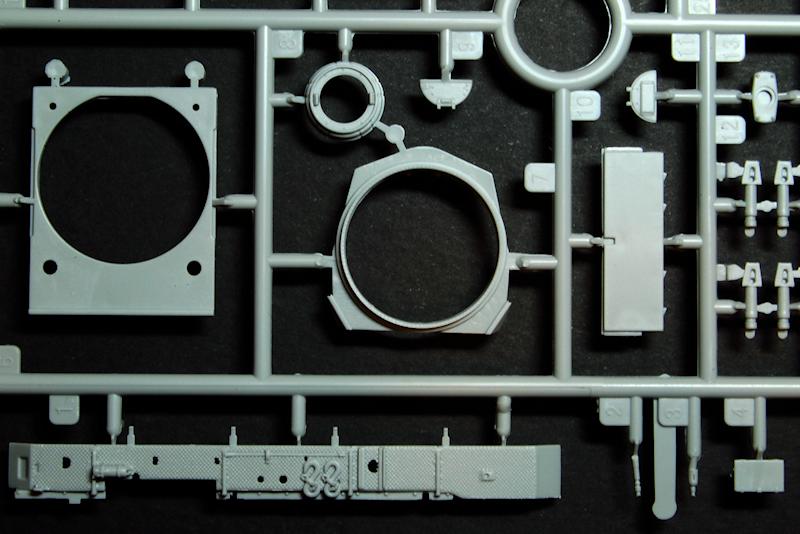
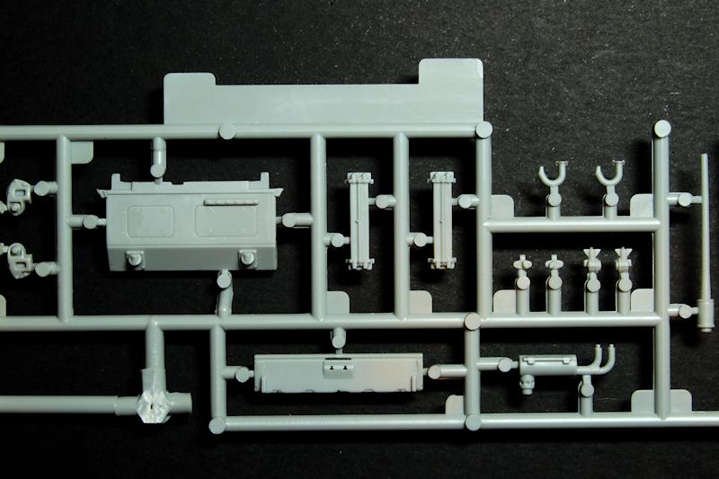
Sprue A holds the generic Pz.Kpfw.III parts. Sprue B has the specific Ausf. M parts, so the muffler, the gun, and the rear hull plates and ancillary parts are all here. Sprue C
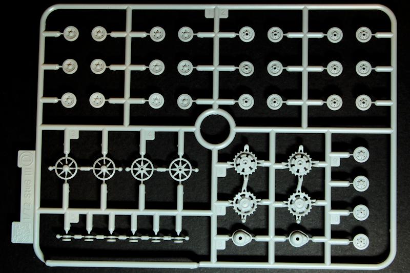
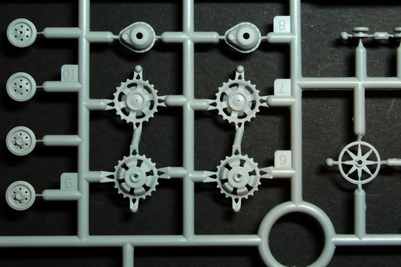
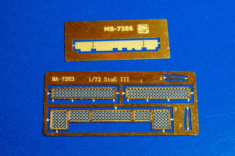
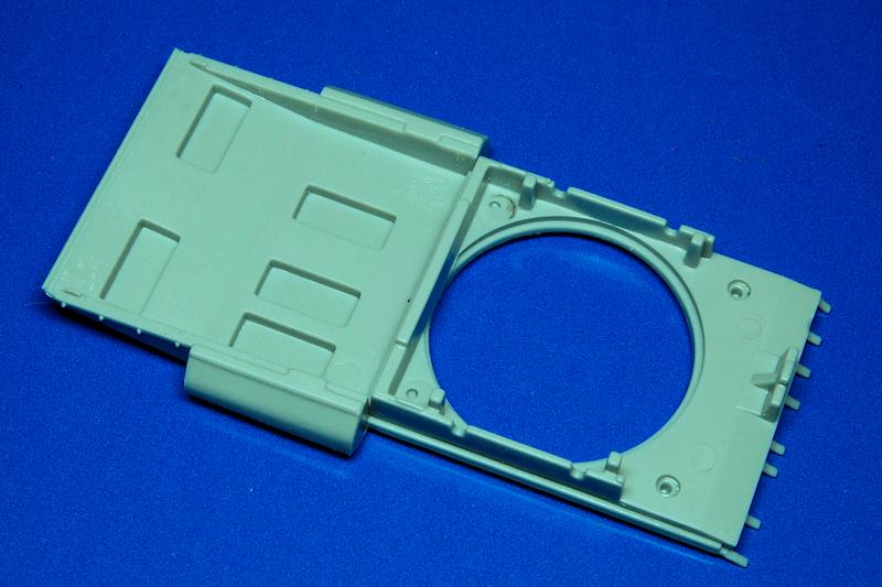
there is no sprue C; sprue D is the wheels and E are the DS tracks. Then theres the one piece hull tub and the top, which just reaches from the turret mounting plate back to the deck. Also included are two tiny photo-etched sheets: MA is the plate that sits over the additional armour that protects the drivers station and is specific to this kit, while MB is the same sheet as originally supplied in the StuG.III.
As pointed out by Jan Etal in his review of the
Pz.Kpfw.III Ausf.N DAK, moulding is of a very high standard indeed in terms of crisp detail, minimal mould seam lines, no flash, and no ejector marks visible after construction. This doesn't always translate to quick clean up of parts however, as there are some awkward sprue attachments, more of which later. Perhaps due to the need for sprue interchangeability, only the sprue with the wheels has a completely neat enclosed appearance; turret shell and mantlet were just floating in the bag with a single piece of sprue attached and theres a number of parts attached around the edge of sprue A, including the two machine guns which are tiny and only protected by a sprue protruberance between them the point here is to take care and not knock these pieces off during handling.
Construction
Although my fellow reviewer Jan, when building the Ausf.N, recommended studying the instructions before building, in this case the modeller is advised to proceed with some caution as the sheet contains a number of errors.
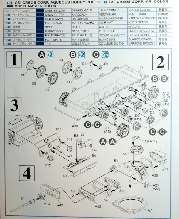
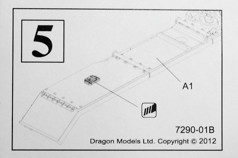
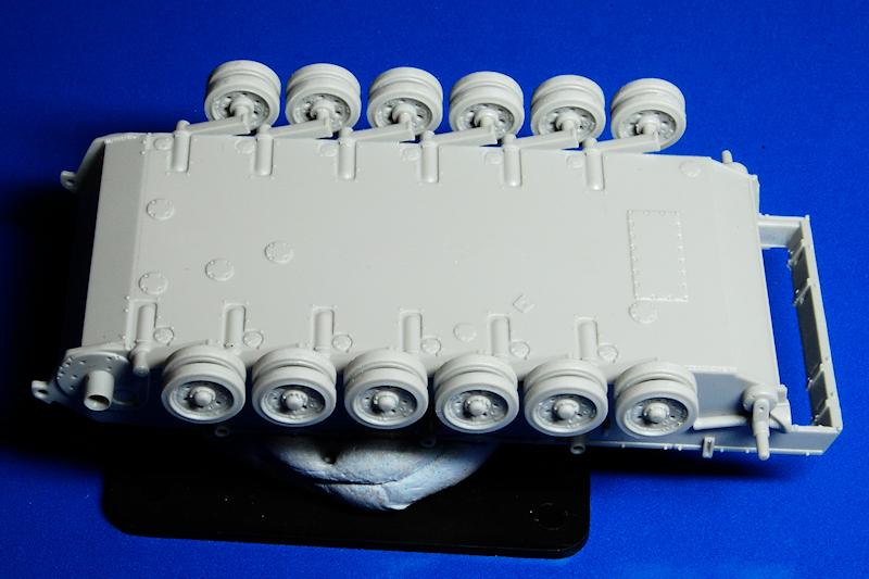
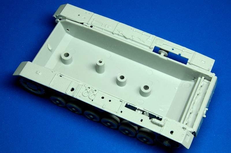
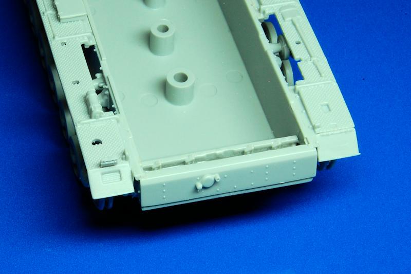
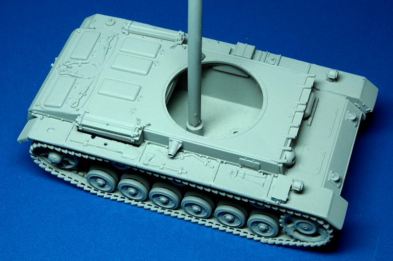
Before starting, I suggest that the very first thing to do is to remove the moulded on location markers for the hull side escape hatches, which are not required for this version. Now to the wheels: two sprocket halves attach to the final drive covers (dont forget this part like I did
) and two idler halves all need to be carefully made to keep teeth and spokes in line. Now dont be confused by the illustration of the return rollers being constructed at 1C, as the picture should actually be of the road wheels, parts D1 and D2; the return rollers, D5, are moulded in one piece so dont need building, just careful clean up.
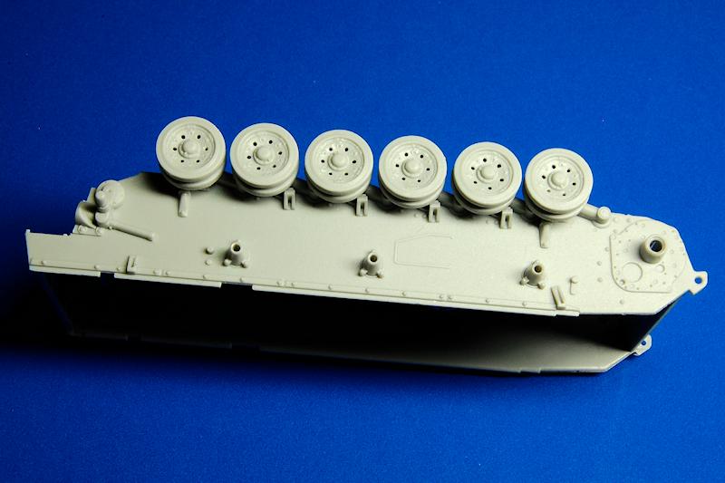
All the wheels go on to the hull in stage 2, along with the additional shocks at each corner. One part I didnt fit at this stage was the, ahem,
spare track link rack on the nose plate for reasons which well come back to.
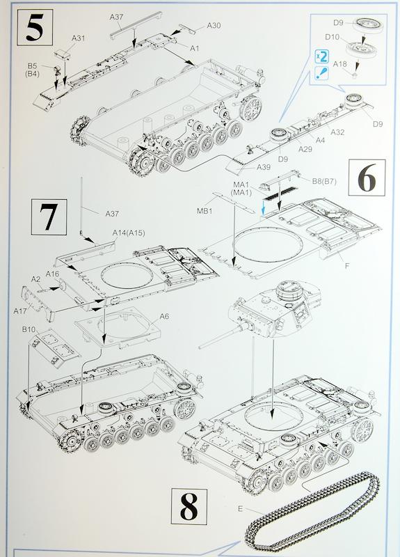
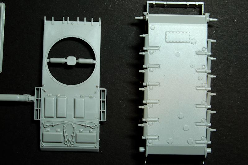
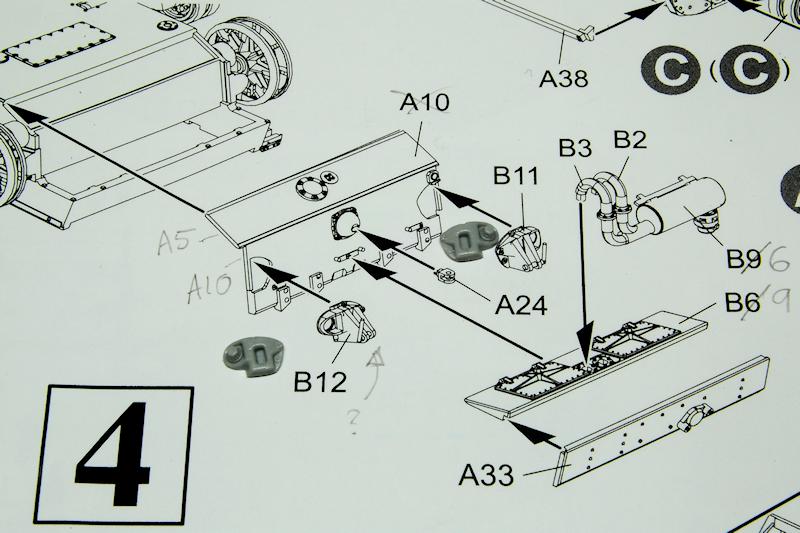
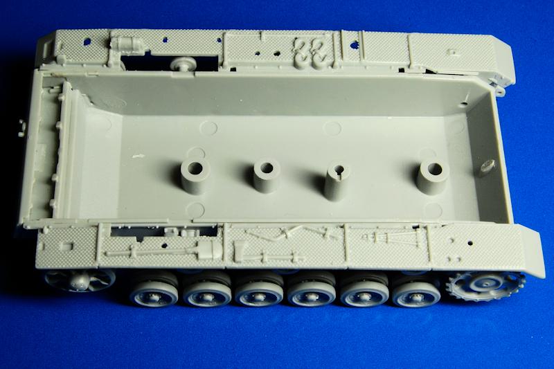
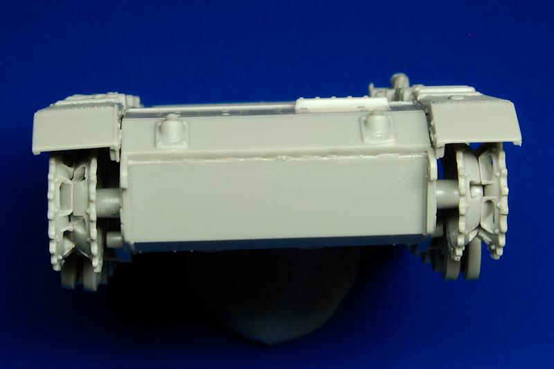
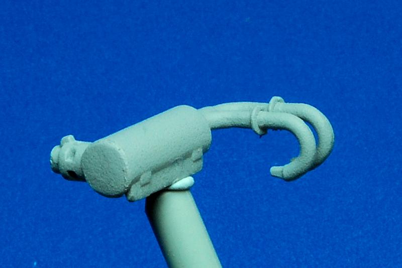
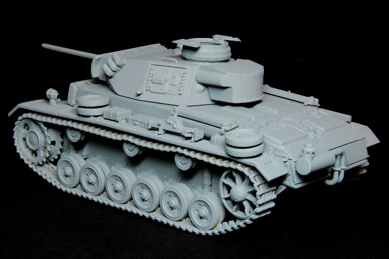
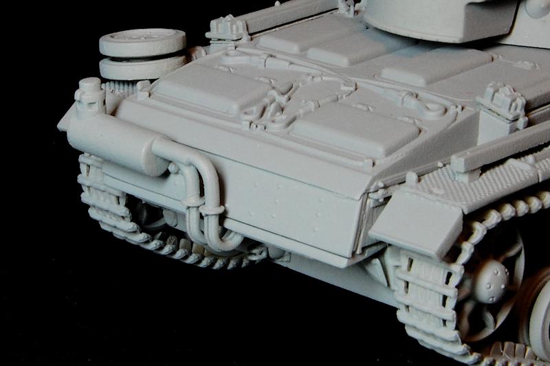
Now we come to the wading muffler arrangement in stage 3, and I suggest allowing the previous work to set thoroughly for several hours before continuing, as the rear plates fit in such a way that theres a fair bit of fiddling around and one wouldnt want to mess up the carefully aligned wheels. This is also where the instructions get a little crazy: theres actually four plates to be added here, while the instructions number it as if there are three; the plate labelled A10 is actually two parts, A5 and A10; the plate labelled B6 is in fact B9 while the exhaust muffler is labelled B9 but really is B6. I would urge careful dry fitting of these four plates; youre kind of making a step shape, and B9, the plate that sits horizontally underneath the body work and has the two holes for the exhaust pipes, has to cover over the empty space at the back of the hull tub. Theres not too much to glue it to, so once the parts were tacked into place, I then joined them up by running cement between them.
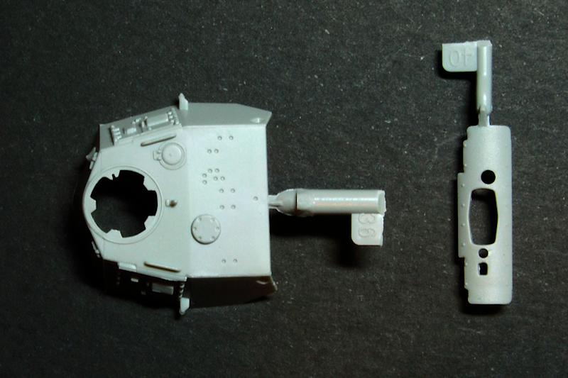
The exhaust pipes and muffler were constructed but put to one side for now. A further oddity here is the rear towing hooks, shown as two single items, B11 and B12; in fact these are just the bases, and they need the addition of the tiny towing eyes and pintles, parts B13 and B14 (photo 30).
From here mostly alternated between steps 4, 5, 6 and 7, on the basis that it is better to leave small cemented parts to set while working on another sub-assembly. So from step 4, the turret top and bottom were glued, then the mantlet and gun elevating mechanism was built, the turret bin parts were combined, and the cupola added to the turret. All these were put aside.
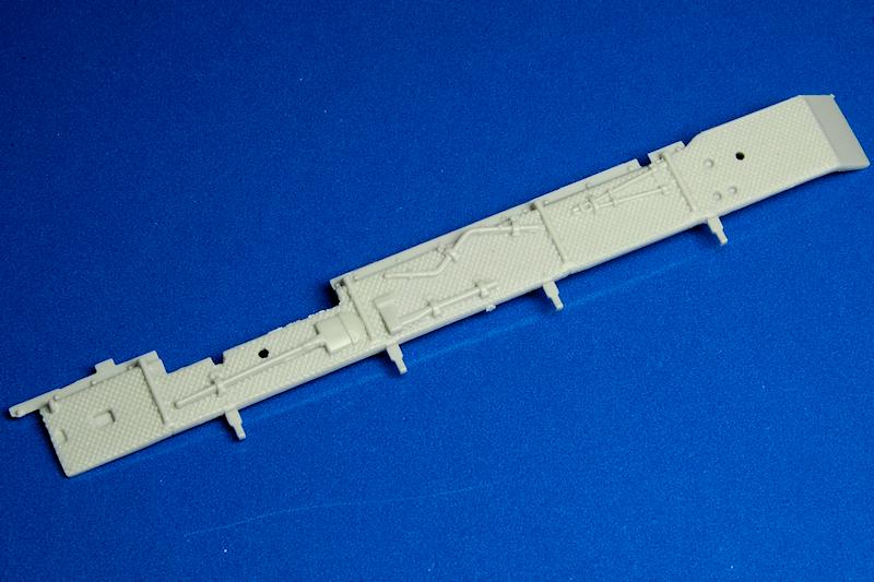
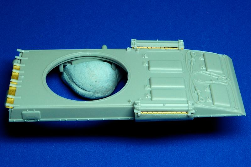
From step 5 the track guards were prepared and added to the hull; again, with not much attachment area, some careful tacking and then strengthening of the joint was employed. The track guards are acceptably thin, but come with all of the tools moulded on, apart from the jack. Note that there is a small detail on the left hand track guard that needs to be removed to allow the headlamp to be attached; I think on some variants this detail is the Notek light mounting, but for this wading version, the headlamps were moved from the superstructure to a higher position on the track guard. The instruction to remove this detail is shown on an erratum slip separate from the instructions, so be sure to find it in the box (confusingly the wrong track guard number is referred to, but it should be obvious which one it is). A fairly large component sits underneath the turret ring that is invisible once built, and this was added, from step 7.
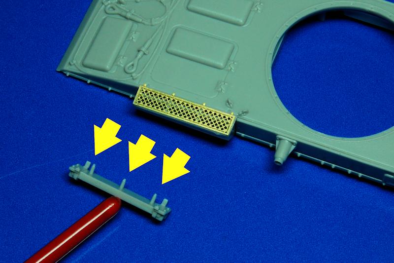
While those assemblies set, the etched mesh engine intake covers, (both MA1) were tackled; these fitted well just make sure theyre the right way up. A cover goes on top of the mesh, parts B7 and B8, and these had a feature I didnt understand: three pins sticking out the bottom (arrowed in photo 36); theyre too thick to go through the mesh, yet it doesnt make sense to me that there should be a large space between the cover and the mesh. Consequently I filed them right down until they fitted as shown in photo 37.
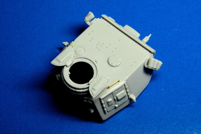
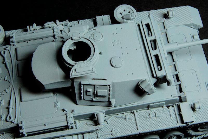
The other etched part to be used, MB1, sits over the space between the front superstructure the drivers vision port / machine gun mount, a perfect fit in itself and the additional bolted armour plate. Another cock-up on my part Im afraid, in that I misread the instructions and inserted this part
underneath the brackets that stand the armour plate off from the superstructure. The result was a fair amount of work to make it fit, when obviously it should just sit on top. Despite this error, I also felt that the additional armoured plate didnt sit well on the plate underneath, and resorted to trimming away material from the back side of it, around the aperture for the machine gun and the cut out for the drivers vision port. This gave the plate a more stable fit rather than rocking around.
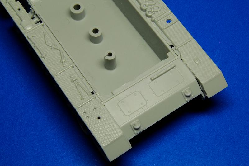
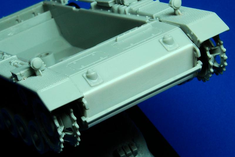
When it came to attaching the sloping front plate, B10, in step 7, I wondered if it would have been better to have added it to the hull before the track guards were fitted, as it seemed to me that the two small projections on the sides should fit underneath the track guards. To an extent this is borne out by the sequence adopted in the instructions for the Ausf.N models where all these parts are fitted in the same step.
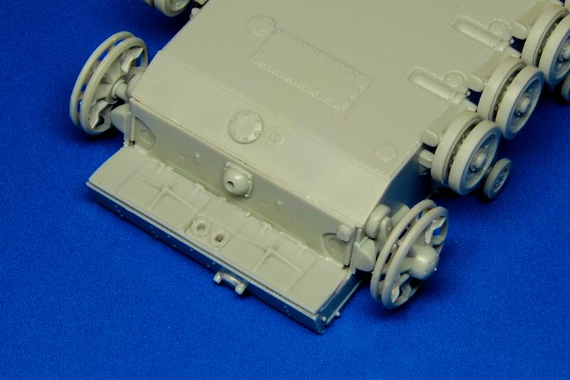
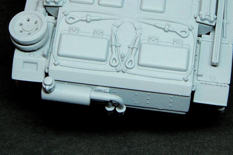
With the sloping plate in place, I thought the way that the nose plate sat
under it just didnt look right when compared to photos (photo 40), which show the nose plate sitting in
front of and overlapping the sloping plate, and being somewhat thicker in appearance. I therefore added an additional sheet of styrene, prior to adding the
spare track link holder (photo 41).
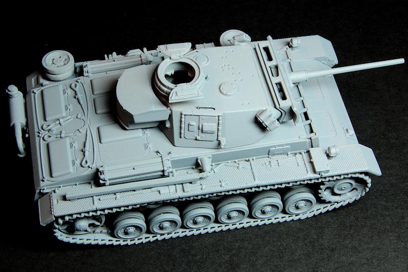
Photo 45 shows the track guards with various details added, and this is where I finally erased the escape hatch markers, as I earlier advised should be done at the start. Although DS tracks can apparently occasionally be of incorrect length I found my examples fitted exactly. I attached these with cement, wanting to get them on before any paint so that they could be glued accurately and securely; once the attachment was set, the next day I introduced sag by inserting cocktail sticks to push them away from the track guards, then set the shape with more liquid cement.
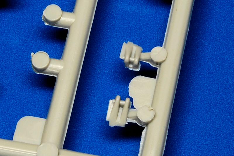
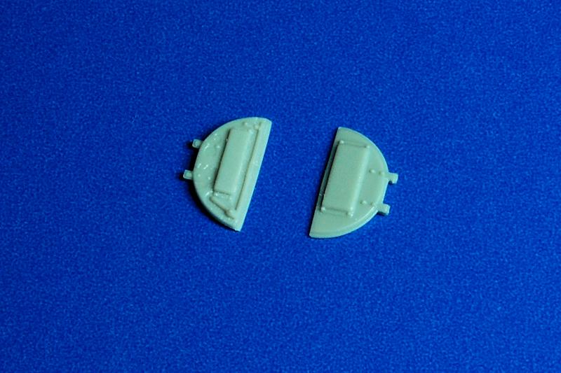
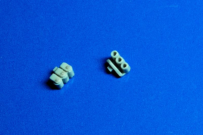
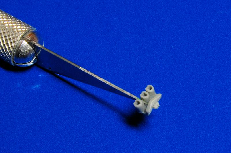
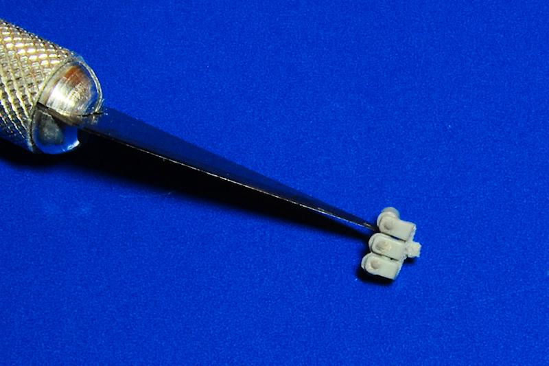
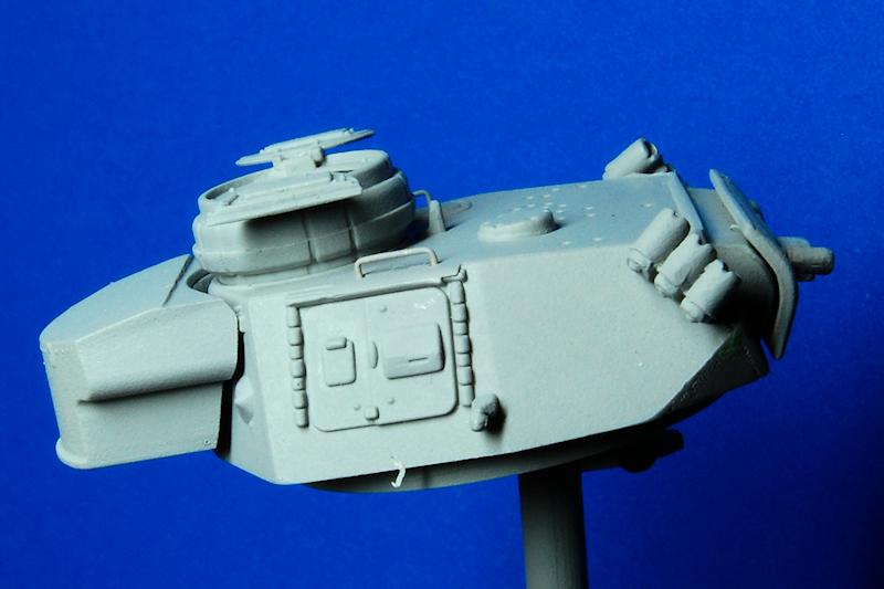
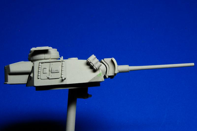
Returning to the turret: the commanders hatch halves have welcome detail on both sides, so I elected to fix them open; they should sit horizontally once opened out. The instructions number the hatch halves as if interchangeable, but they are not identical; A9 has the handle and, if closed, should sit with its closing edge over that of A11. The smoke grenade launchers are slightly wrong in that the three tubes are all aligned, when they should actually be raked in slightly differing directions. They also lack any detail on the bases of the tubes so I added some Grandt Line rivets, and also drilled the tubes to make the walls a little thinner. The tubes were carefully separated with a knife, and I tried to then bend each tube into a slightly different direction by inserting a drill bit to use as a lever. This wasnt very successful, and on reflection, it would be better to completely separate the tubes and then re-cement them into a suitable configuration. It has to be stated however, that these things are pretty fiddly at this scale. A little more detail was added in terms of removing the solidly moulded grab handles and replacing with copper wire, and also some welding texture was embossed into the join around the mantlet.
The instructions show the aerial stay, A37, going on in step 5, and then a separate aerial, also labelled A37, being attached in step 7; these are actually not separate items, and theres no option to have the aerial upright. Instead they are moulded together with the aerial already stowed. It probably wouldnt be too hard to depict an upright aerial by channelling out the stay and using the mounting bracket as the base for a scratched aerial.
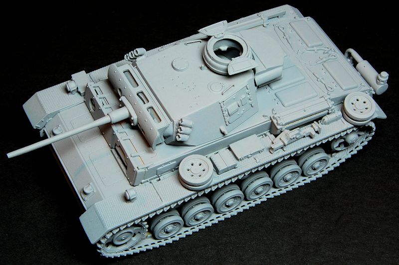
The hull top was attached to the bottom and, and then, with the turret stowage bin, the gun and mantlet armour, and the exhaust assembly all still separate, I primed everything. This is because there are some visible open spaces between some of these parts and I wanted to be sure that all the surfaces were at least coated in primer before assembly. Once dried, the final assembly was completed.
Conclusion
First of all, apologies for my own mistakes in this build
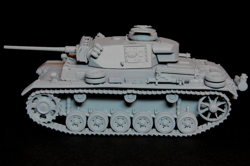
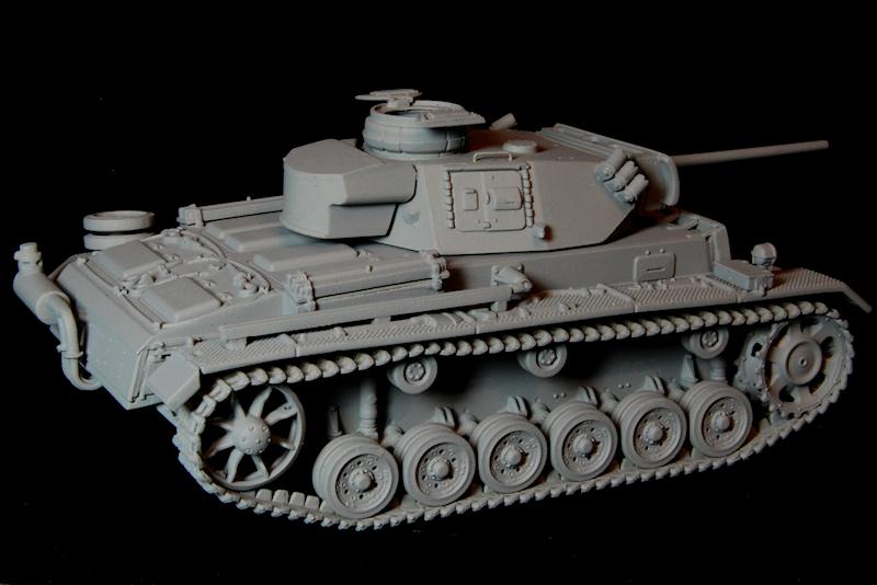
all my fault and nothing to do with the kit or the instructions. This kit is broadly similar of course to the other Pz.Kpfw.III variants that Dragon released this year; the rear end does have an appearance which is quite distinct from that of the Ausf.L, as can be appreciated in photos 63 to 69, although this type of wading muffler also appears in the two Ausf.N kits, so is not unique to this kit despite the with Wading Muffler billing on the box. Its worth noting that this kit would be pretty easy to convert to an Ausf.M F1 Flammpanzer with its thick and straight flame projector barrel (hows that for tempting Dragon into just one more variant?)
Id say that for a small model, this was a comparatively time consuming build, and I concur with some of Jan Etals observations regarding sprue attachment points. Some particularly troublesome examples featured rather thick wedge-shaped attachments where special care was needed to avoid levering the part against the sprue while trimming it off, so as to avoid tearing the part from the sprue. I guess this is where sprue cutters offer an advantage over using a knife.
On the negative side, it is a shame that the instructions are frankly a bit of a debacle, but thats almost normal for Dragon from what I have seen (one more error the tracks are shown upside down in step 8). Then there are the slight weaknesses I picked up in terms of the smoke launchers and what I feel is a wrongly designed nose plate. The aerial is an odd one in that it could quite easily have been done in two parts as per the instructions, but wasnt, which again brings to mind the comments made in Jan Etals review of the Ausf.N (DAK), that these kits go into great detail in some places, then go for what almost seems like unnecessary simplification in others. As for the spare track links well, where are on earth are they? Virtually every photo of a Pz.Kpfw.III shows a length stored on the nose at least, if not elsewhere as well, so it is really an omission not to include some, and for the relatively high cost of this kit, not a justifiable one.
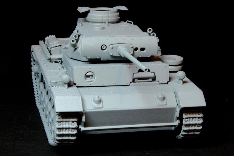
On the positive side, I actually ended up thinking that this is just about the most beautiful 1/72 scale kit Ive built, and one that really does give an example of how small scale kits have been developing in recent years. It is noticeable, I think, in the photos of the completed primed model, that the proportions of the details are very well scaled, and really do bear comparison with larger scales in terms of having the authentic look of the real thing. Some dedicated 1/35 scalers might be pleasantly surprised if they were to pick this little kit up.


Comments