Background
The M42 40 mm Self-Propelled Anti-Aircraft Gun, or Duster, was an armoured light air-defence gun for the US Army. It was based on the chassis of the M41 Walker Bulldog light tank. The 500 hp, Continental AOS 895-3, 6-cylinder, air-cooled, petrol engine was located in the rear of the vehicle. In 1956, production changed over to the M42A1 which was powered by a fuel-injected version of the same engine (Lycoming AOSI-895-5, also of 500 hp but producing more torque). The M42 was produced by ACF Industries until December 1953 and at the Cleveland Tank Plant until June 1956. 3,700 vehicles had been manufactured when production ceased.
The vehicle weighed 22,500 kg (49,500 lb) fully loaded. Maximum speed was 45 mph with a range of 100 miles. Armament consisted of fully automatic twin 40 mm M2A1 Bofors with a rate of fire of 240 rounds per minute and either a .30 calibre Browning M1919A4 or later a 7.62 mm M60 machine gun. A standard operating crew would be between four and six.
The earlier M42 had a hull roof that was split between the crew hatches (the driver sat on the left, the commander on the right). These could be opened, along with the crew hatches for an unobstructed opening for loading ammunition in the hull stowage racks. On the M42A1, the split top was deleted and replaced with a simplified one-piece plate (both alternatives are included in the kit). Other minor changes included revised headlights. Later Dusters had three-pronged flash suppressors fitted to the muzzles replacing the simpler conical flash hiders of the M42. Many Dusters seen in action photos in Vietnam had their flash suppressors removed, so check your references. The later production M42A1, as depicted in this kit, had an exhaust silencer for the auxiliary power unit mounted above the main engine exhaust silencer on the right and a field telephone box on the hull rear.
The Duster was developed out of experience from the Korean War. During the course of the war, the US Army decided to phase out all vehicles based on the M24 Chaffee chassis, including the M42s predecessor, the M19 Gun Motor Carriage 40 mm Anti-Aircraft, in favour of designs that utilised the chassis of the M41. Since the 40 mm guns were still seen as an effective anti-aircraft weapon, the gun mounting of the M19 was simply grafted onto to the M41 chassis with minor changes including a partial redesign to accommodate the larger mounting ring of the M41. Initially, it was proposed that the guns would be aimed with the assistance of a radar fire-control system housed in a secondary vehicle of similar design, but this idea was scrapped as development costs mounted.
In the late 50s, the US Army reached the conclusion that anti-aircraft guns were no longer viable in the jet age and began fielding a self-propelled version of the Hawk surface-to-air missile instead. Accordingly, the M42 was retired from front-line service and passed to the National Guard with the last M42s leaving the regular Army by 1963, except for the 4th Battalion, 517th Artillery in the Panama Canal Zone, which operated two batteries of M42s into the 1970s.
Unfortunately, the Hawk missile system performed poorly in low-altitude defence. To ensure some low altitude anti-aircraft capability for the ever increasing forces fielded in Vietnam, the Army began recalling M42A1s back into active service and organised them into air-defence artillery (ADA) battalions.
Three M42A1-equipped ADA battalions were sent to Vietnam, the first of which arrived in late 1966. Despite a few early air kills, the air threat posed by North Vietnam never materialised and ADA crews found themselves increasingly involved in ground-support missions.
It wasnt until the Vietnam War that it earned the nickname Duster and was referred to as the M42 Duster for the remainder of its service with the US Army.
The Duster became a key infantry support weapon in the Vietnam War. It was used with the manoeuvre forces against low-altitude air attack. In addition, because of the rapid rates of fire, the gun proved to be effective as a support weapon against ground targets. The M42 was used frequently on point security, convoy escort or perimeter defence. The rapid firing guns could devastate massed infantry attacks or sweep away guerrillas hiding in the jungle with relative ease.
The last M42A1-equipped ADA units left Vietnam in 1972 and the Duster was returned to the National Guard. The US Army maintained multiple National Guard M42A1 battalions as a corps-level ADA asset until the system was retired in 1988.
The M42 was also used by Germany, Greece, Japan, Jordan, Lebanon, Pakistan, Taiwan, Thailand, Turkey and Venezuela.
contents
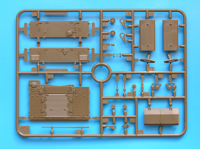
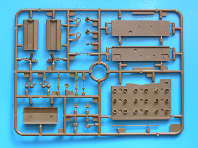
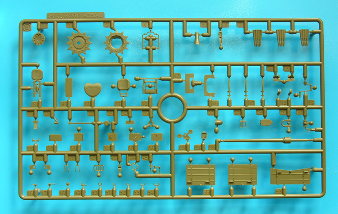
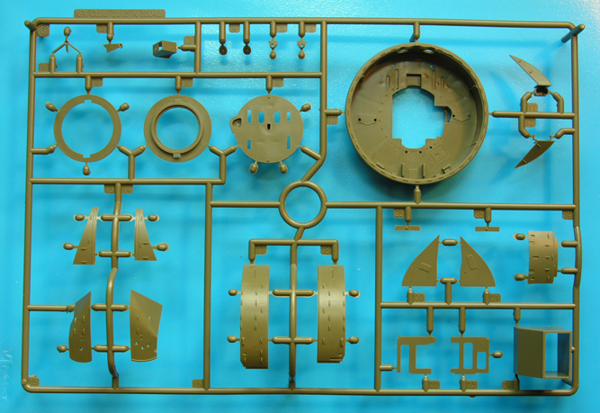
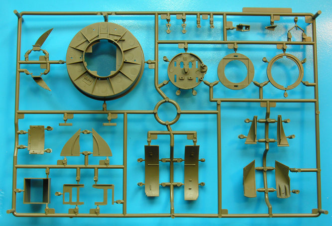
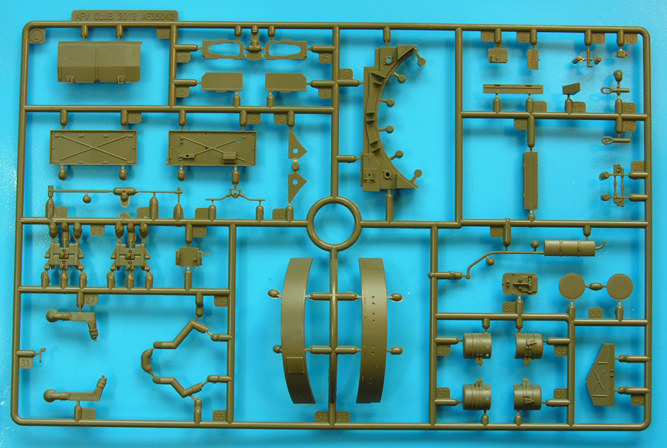
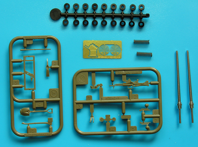
Upon opening the box you are presented with eleven sprues containing the majority of the 442 parts. Also included is the hull tub, a sprue of polycaps, two metal springs, two turned aluminium barrels, one small brass fret, string, two vinyl tracks and a decal sheet. As with other recent
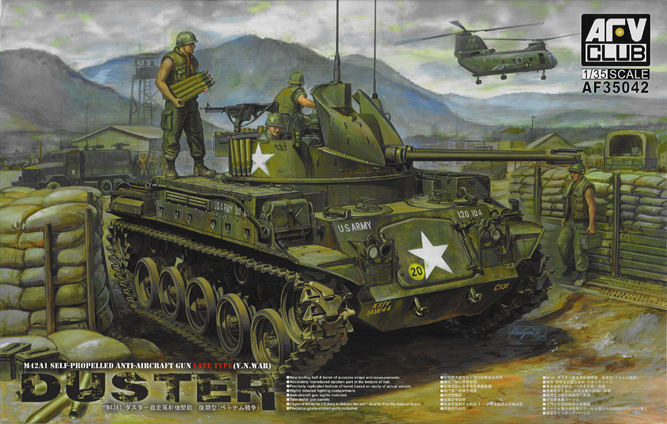
AFV Club kits, also included is a print of the box-top art. All of the sprues have identification letters and part numbers. The contents are:
Sprue A - rear deck grilles, various lifting eyes, headlights, tail lights, exhaust silencers, aerials.
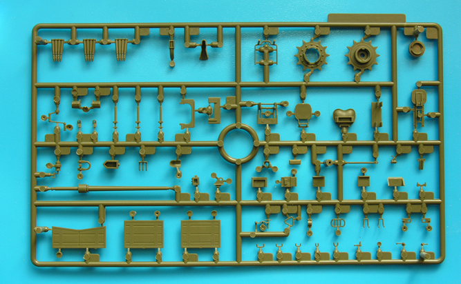
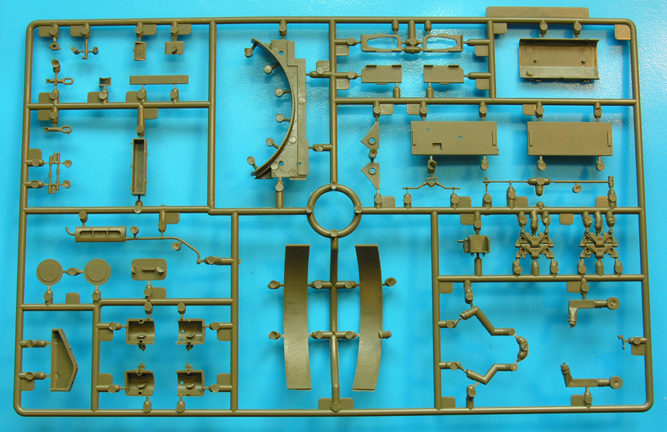
Sprue B x 2 - sprocket (not used here), ready ammunition, crew seats, main armament barrel, ammunition box lids, various small details including clamps, handles and tie downs, gun recoil mechanism.
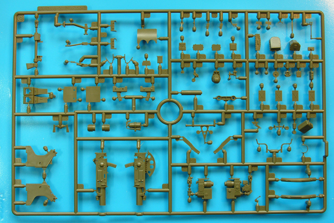
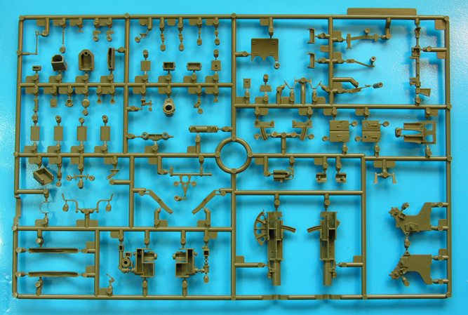
Sprue C - mostly gun mount parts including breech, control system/computer sight.
Sprue D - main gun mount components tub, walls, shields.
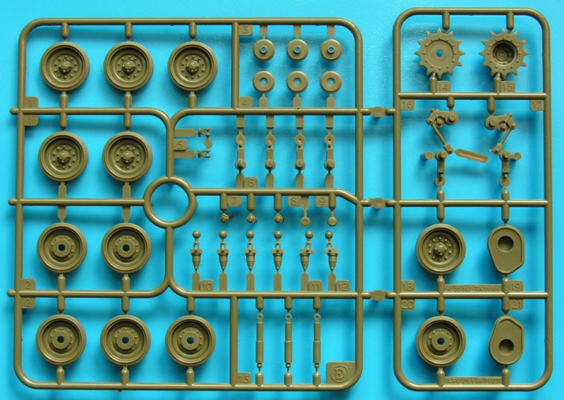
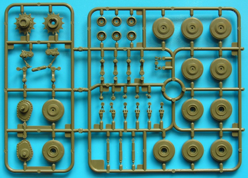
Sprue E x 2 - road wheels, idlers, sprockets, dampers, bump stops, idler adjusters.
Sprue F - tools.
Part H - two metal springs.
Sprue I - polycaps.
Sprue K - parts for M60 machine gun
Part N two turned aluminium barrels.
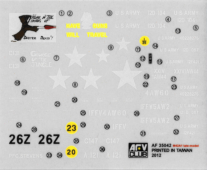
Part J - Decals - with five vehicle options and string for tow rope.
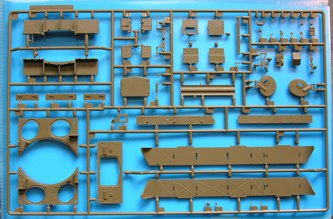
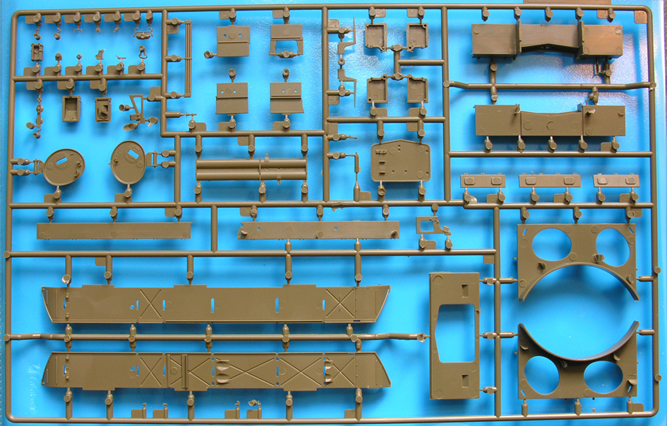
Sprue L - rear hull parts including air filters, spare track links, hull shields, exhaust heat shields
Part M- Photo-etch fret with aiming sights, APU exhaust guard.
Sprue O - more hull parts including glacis plate, glacis hatch and stowage boxes, crew hatch plate (two variations early and late incorrectly marked as J40 in the instructions), crew hatches, jerrycans, track guards, ammunition boxes.
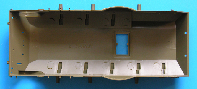
Part P - hull tub.
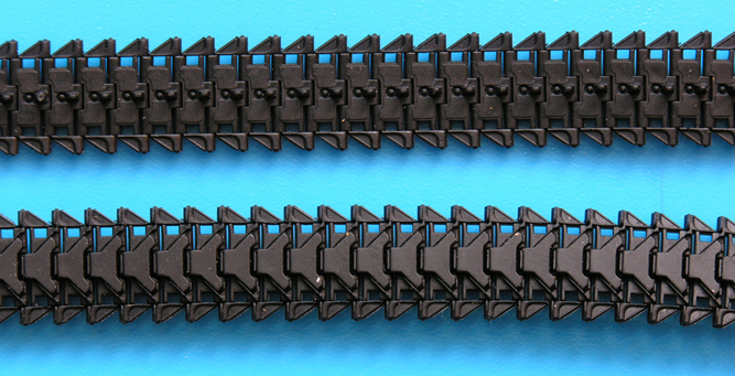
Part T x 2 full length vinyl tracks
There are no clear plastic parts.
A small addendum sheet is included to correct four stages in the instructions. It is best to mark these so they are not forgotten, but there are other mistakes not noted on this sheet.
First Impressions
The overall quality of the parts is very, very good with excellent moulding and superb moulded-on detail throughout such as innumerable tie-downs, weld lines, ribs, hinges, etc. There is some minor flash on some parts but nothing to worry about. As is normal with AFV Club kits, there are many small parts attached to the sprues that will need careful removal and clean up. Some of the larger parts such a the ammo boxes, exhaust silencer guards and hull roof parts have some large ejector pins which, though they will not be seen when completed, will need to be removed for a good fit.
The kit includes sprues from the Skybow/AFV Club M41A3 kit, mainly for the running gear and the engine deck. Two alternative drive sprockets are included more on this later. AFV Club already produce a separate kit for the M41s running gear (AF35045) designed to update the old Tamiya M41 and M42 kits, so it seems strange that they have not adapted this in the Duster kit. This set includes sprockets with lightening holes - which are included in this Duster kit! - and separate outer road wheel tyres for better definition. If you decide to use this option, please be aware that the stub axle diameters are completely different and you will need two sets as the Duster has six road wheels and idlers which are identical. The M41 had five road wheels and a different idler. To my eyes, the separate set has mounting bolts which are slightly over scale, whereas the Dusters appear to me to be slightly under scale.
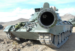
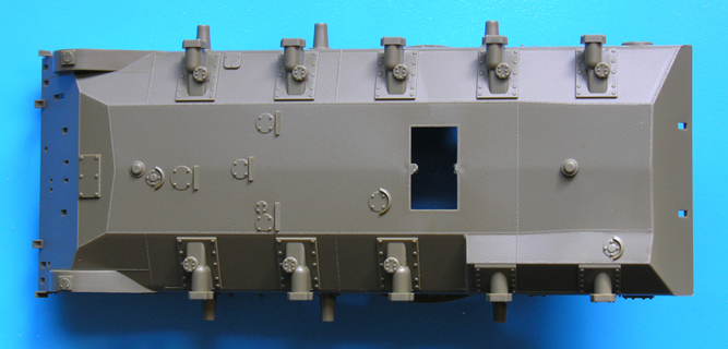
The lower hull is supplied as a conventional tub. A feature of the lower hull is a bulge over the first two axle mounts on the left. I havent a clue what this is for, but there seemed to have been two designs. Whether this is a product of different factories or a design feature between early and late models, I cannot tell. This kit has the bulge at a downward angle, though the box top art features the alternative flat design which is parallel to the hull bottom, but stepped down. Interestingly, the box top art for the soon-to-be-released Early M42 also has the same feature. Which is correct I dont know, perhaps someone can enlighten me. Most of the reference photos I have seen also have the stepped flat bulge. It will be interesting to see if AFV Club give us a different hull tub for the early version.
The gun mount includes a large amount of intricate detail so it is a pity that there is no hull interior detail to show below the crew hatches. If the glacis door is left open, this will become particularly evident.
There are no building options apart from alternative colour schemes and decals.
No crew figures are supplied.
Instructions:
The instructions are presented as a 20-page, A4 stapled black and white booklet. Each step is illustrated in a logical order with beautifully clear and large line drawings. There are 43 steps in the construction process and I cant imagine many problems being encountered although some of the steps are quite dense - though easy to understand - with many small parts to be added.
going through the steps
The build commences at the bottom. Stage 1, not surprisingly, starts with the lower hull tub to which are added suspension bump stops, transmission covers and front towing eyes. In Stage 2, dampers, suspension arms and the idler mounts are all fitted before adding return rollers and sprockets in Stage 3. Here we hit a small problem. The instructions tell you to use parts E14 and E15 for the sprockets. Dont!! These are from the old Skybow M41 kit. However, the kit also includes better sprockets B1/B2/B3 (plus polycap) which originated in the separate M41 suspension kit mentioned above. These have been engineered to have lightening holes around the hubs, so use these and not as per the instructions. The road wheels, idlers and some rear hull detail is added in Stage 4. In Stages 1 and 4, the addendum sheet points out that the front and rear towing eyes have been incorrectly numbered. In Stage 5, the detail of the rear hull is completed with the addition of lights, tow hook, crow bar and lifting eyes.
A feature of the hull is a rectangular hole in the floor which is the bottom of the shell ejection chute. This has the gun mount ring attached to the top and Stage 6 of the instructions has you gluing these two important parts in at an early stage. It might be wiser to leave this until the gun mount is complete to ensure it sits correctly inside the shields in the hull top.
At Stage 7 we start on the upper hull work with the rear curved gun shield being attached to the front-most section of the engine deck. Three delicately moulded hoops are then attached to the shield.
Turning to the front hull top, the commanders and drivers hatches are detailed in Stage 8 with periscopes (not in clear plastic as is the norm these days) and delicate handles and periscope guards very nicely done in plastic. Stage 9 brings up another instruction mistake. Two hull roof plates are supplied for early and late versions as noted above. The part to use here is
O40 and not
J40 as suggested incorrectly in the instructions.
Stages 10 and 11 detail the glacis access hatch. On Late M42s, the inside of the door became cluttered with the mounting of a .30 calibre ammo box, flashlight clips (very nicely moulded) and a large periscope box. All of this is correctly depicted along with the large external spring and various latches and catches. The inside of the door has three ejection pin marks, two of which will have to be carefully removed. In Stages 12 to 14, the later style headlight arrangement and guards are added, the glacis is attached to the hull front and the engine deck plates mounted. The headlight guards here are a little disappointing compared to the previously mentioned delicate hatch handles and periscope guards. They are a little on the clunky side but some gentle work with a file will have them reduced to scale thickness (I suggest) after they are fitted.
In Stages 15 to 17 the instructions show us how to build up the rather complex left-side track guards and all of their paraphernalia. This includes an exhaust silencer and guard, barrel trays, two spare barrels (which use real springs), ammunition boxes, jerrycan, air filter and spare tack stowage. In Stage 15 (and later in Stage 18) the instructions miss mentioning exhaust deflectors should be added to the pipes. These are parts B26 and B31. Watch out for the addendum to Stage 17 where the barrel brackets have been transposed in the instructions.
Moving on to Stages 18-20, the right track guard is built up in much the same way with its associated exhaust silencer and guard, tool stowage tray, a second air filter and jerrycan and combined ammunition/stowage boxes. In Stage 20 another instruction blooper is that the rearmost stowage box door is incorrectly marked as O33 and should be O31. The track guards are then attached to the hull in Stages 21-22 together with some extra detailing. A small correction that needs to addressed is that the brackets that hold the tow cable on the side of the right-side ammo boxes should be curved and not flat. The work on the hull is completed in Stage 23 with the fitting of the auxiliary power unit exhaust (drill out the end for a better appearance) and its guard, one piece of which is from the small etch fret. Intake pipes are then fitted between the air filters and the engine deck.
One thing completely missing from the instructions is the addition of a telephone box on the right rear hull. The parts are included as parts L7, L8 and L25.
I have been careful not to call the gun mount a turret. Officially, this is how it was described so Ill stick to official nomenclature. The turret build - sorry, gun mount - starts at Stage 24 with detail being added to the circular floor tub. There is some nice detail on the bottom but it will never be seen when mounted. Maybe its just as well as there are no less then fourteen ejector marks to remove on the underside. The central part of the floor is part D9 and this definitely has to have six ejector marks removed. Most of this will be hidden under the guns when finished, but why didnt AFV Club flip this part over on the sprue when they designed it to avoid the ejector mark problem? Numerous boxes cover the floor of this area and two loaders seats are provided which automatically fold up against the rear wall when not in use, so dont portray them folded down unless crew figure is sitting on them. This is all detailed in Stages 25 and 26 which ends with the addition of the two curved chutes designed to catch used cartridges before they fall out of the bottom of the vehicle.
Two further seats are now constructed in Stage 27 for the gunner on the left and computer sight operator on the right. Also added here is the left-side trunnion for the guns. In Stages 28-30 the instructions take us through construction of the twin breeches and the front central shield. Elevation cylinders with operable telescopic arms are built in Stage 31 before adding the gun breech, right-side trunnion and the elevation gearboxes on both sides in Stages 32 and 33. Nicely moulded clips of four shells each can be slotted into the chutes on top of the guns. The guns computing sight is constructed and mounted in Stages 34 to 36 which includes the only other photo-etch parts for the sighting rings.
The last stages take us through the fitting of the guns shields with various fittings on both inside and outside surfaces including the aerial mounts on the front shields either side of the guns. The final addendum is in Stage 39 where they point out that part C53 is, in fact, two parts C53 and C54. The final additions are the turned metal barrels with their three-pronged suppressors and the self-defence M60 machine gun. The flash suppressor (part B25) mentioned in the instructions would be the most common type for Vietnam use. However, they were prone to cracking. This could be why so many were removed completely as mentioned above. One last thing not mentioned in the instructions is an alternative flash suppressor which combines three prongs (parts B17) and a triangular reinforcing ring (part B44) early versions of this type lacked the reinforcing ring. This type would be appropriate for the MERDC colour scheme suggested on the last page.
The very last addition are the tracks which are moulded as one piece vinyl and carry excellent detail as we have come to expect from AFVs tracks. There are no ejector marks, gaps between links (as there should be) and the only clean up is where the track ends meet.
Decals:
These cover five options (with thanks to Terry Ashley of PMMS for identifying the units):
1-44th Artillery Vietnam 1967 - Overall Olive Drab
4-60th Artillery (George of the Jungle) Vietnam - overall Olive Drab
4-60th Artillery Vietnam - overall Olive Drab
5-2nd Artillery Vietnam - overall Olive Drab
From available photos, none of the above should have any flash suppressors fitted.
MERDC camouflage scheme - unidentified unit. Should have later suppressor not mentioned in the instructions. Thankfully, the instructions show all six sides of the vehicles colour scheme.
The Competition:
Just the old Tamiya model. I have never owned this kit, but Im sure any comparisons are completely superfluous.
Conclusions
This is indeed a very fine kit. It is quite a complex model with a lot of detail packed in. It is one of those models that has the WOW factor if you are into complicated self-propelled machinery. The instructions seem daunting at first, but the construction is perfectly logical and I dont see any problems for any modeller building this machine. From the action photos I have seen, the Duster is blissfully clear of external stowage unlike many American vehicles. It is a shame there are a few bloopers in the instructions with some parts not even mentioned, but I hope Ive pointed them all out. Dont let this distract you from what is a superb model.
References:
M42 Duster Walk Around, Squadron Signal Publications, number 5705
Sheridan, A History of the American Light Tank, Volume 2, R.P. Hunnicutt, Presidio Books
Website references:
Excellent photos taken in Vietnam from Jerzy Krzeminski
militarymodelling
Primeportal/Marcel von Hobe
Primeportal/Brent Sauer
Facebook


Comments