History
By late 1941 both Porsche and Krupp were heavily involved as the first team in the process of designing a tank to utilize the long 8.8 cm gun. Porsche was tasked with the designing of the chassis and Krupp for the designing of the turret. Porsche believed that the chassis for the VK45.01 (P) could easily be modified and adopted over to mount the turret being designed by Krupp for the 8.8 cm gun. Porsche proposed two sloped armor modified chassis versions, one with turret mounted to the front (Vorne), and the second one mounted to the rear (Hinten), with the former being chosen for series production.
Plans were then set for the installation of turrets with the 8.8 cm Kw.K. 43/2 L/71 gun starting with the 101st Pz.Kpfw.VI VK-45.01 (P). Negating a contract for a trial series vehicle, contracts for procurement to fabricate the needed components and for series production assembly of 100 VK45.01 (P2) vehicles were awarded by February 1942. The contracts stipulated that the first six VK45.01 (P2), Typ 180 vehicles with turrets for the 8.8 cm Kw.K. L/71 gun be assembled and operational for scheduled delivery by November 1942. However, due to problems with the Porsche designed engines and suspension the contracts for the series production program of the 100 vehicles were repealed on 3 November 1942.
Late in that same month a series of conditions led to the reversal of the previous cancellation and contracts were again awarded but this time for only three VK45.02 (P), Typ 180 vehicles were to be completed. The already fabricated and welded 50 turret bodies by Krupp, on the original contract, were eventually excised over for use on the initial Henschel Tiger H2-Series (Tiger Ausf.B - Tiger II) program, hence the inaccurately identified Porsche produced turret. And the 90 Porsche Typ 180 lower hull assemblies were eventually modified for use on the Ferdinand series produced vehicle.
By the end of January 1943 Krupp reported back to Wa Pruef 6 (Automotive Design Office of the Ordnance Department) that the three turret armor bodies had been readied and the three armor hulls had also been completed and delivered to Nibelungenwerk. By mid February 1943 Krupp again informed Wa Pruef 6 that the three vehicles were being completed with electrical drive and new suspensions. A delivery date had not been set.
A year later in late April 1944 Krupp reported that only one turret had been fully assembled and readied and promised maximum effort to complete all three turrets for use in the Tiger H2-Series (Tiger II). And finally in mid August 1944, it was reported by Krupp that all three turrets had been converted to the Henschel model hydraulic turret traverse drive.
No further information has since surfaced concerning the final outcome of the three Krupp turrets with the 8.8 cm Kw.K.43 L/71 gun or of the three Porsche, Typ 180 chassis. To date there are no known photographs of the PzKpfw. Tiger P2 VK45.02 (P) vehicles. There has been some speculation of at least one of these vehicles being operational as part of Panzer Kompanie Kummersdorf. This is due to an 8.8 cm L/71 gun P2-Turm turreted Porsche Tiger being listed as part of that group on March 1945.
The following project designations are only for the three known vehicles being produced.
Porsche had its own designations for their chassis design, that being:
Typ 180 - for electric drive
Wa Pruef 6 had their official designation:
PzKpfw. Tiger P2
The official designation for this vehicle as per the Jentz & Dole VK45.02 to Tiger II book:
PzKpfw. Tiger P2 VK45.02 (P), Porsche Typ 180
Porsche had been experimenting with several engine and chassis combinations those being:
Typ 180 - for electric drive (including a number of engine / horsepower / fuel combinations)
Typ 181 - for hydraulic drive (same as above but with hydraulic drive)
This amounted to having a pair of engines and generators coupled together to power two large electric motors slaved to each track drive wheel. One of the proposed combinations only used one engine generator to power the two electric motors.
Thanks go out to the team of Jentz & Doyle for their dedicated hard work and research through puzzling together the few surviving original line drawings, documents and records that has brought this obscure vehicle to our attention. And thanks to the Cyber-Hobby team that we now have this obscure vehicle in plastic.
contents
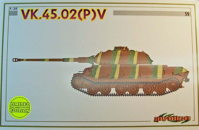
This is
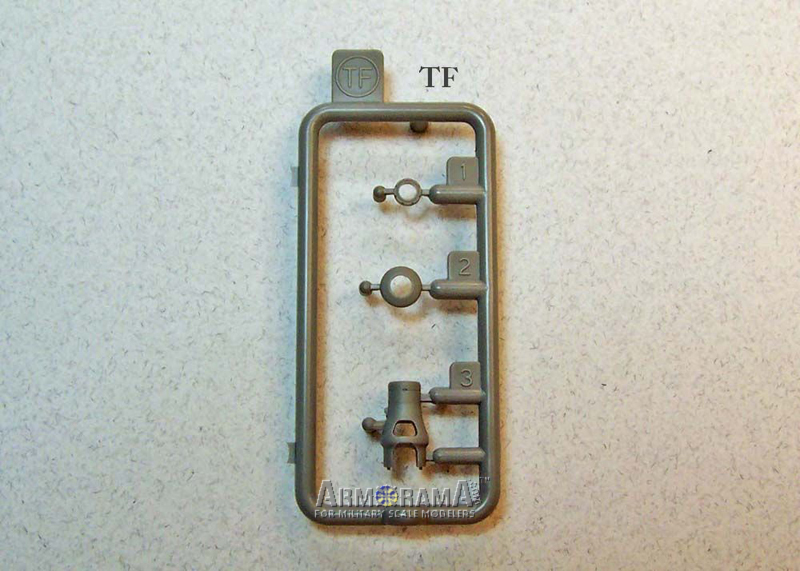
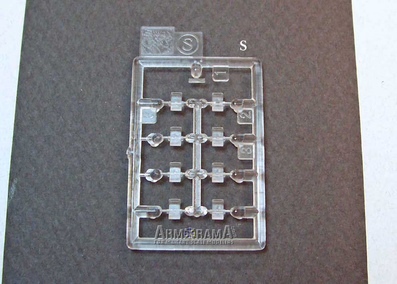
Cyber-Hobbys No. 59 limited edition white box release. A multi- media 1/35th scale styrene kit of the VK.45.02 (P) V, kit No. 6613. The unassembled light gray injection molded styrene parts include 338 pieces with 21 of those being clear. One photo-etch fret containing 106 pieces, one turned aluminum gun barrel, two soft styrene lengths of DS100 tracks, two different diameter lengths of braided metal wire, one metal rod, one sheet of water-slide decals and one printed sheet containing six pages of assembly instructions in 11 separate steps.
Molding, detail and fit is to current high industry standards with no visible knock out pin marks on any of the appearance side of the parts with light to almost non-existent mold seam lines, making clean up a breeze. The photo-etch parts are thin and care should be taken when removing and bending them when applicable.
the kit in detail
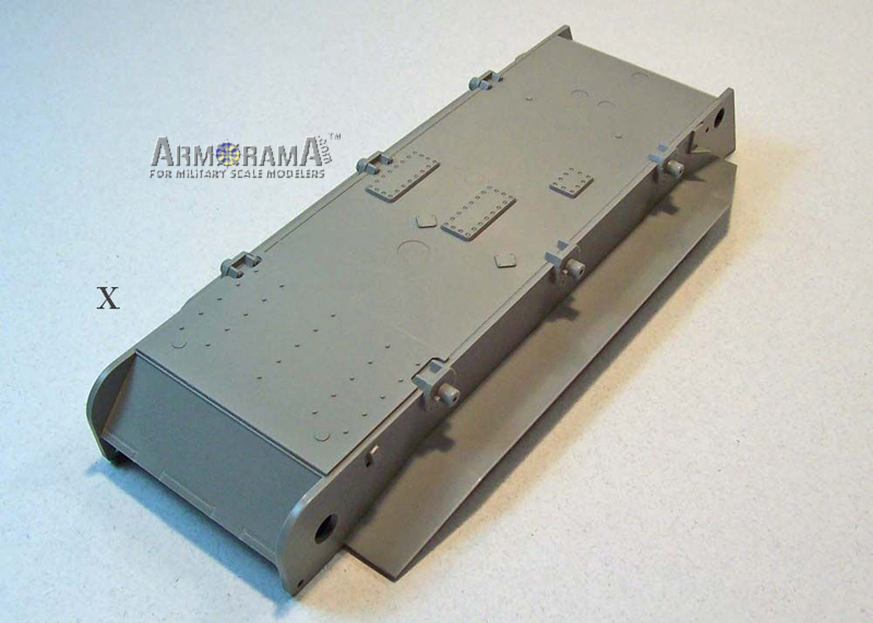
Lower Hull:
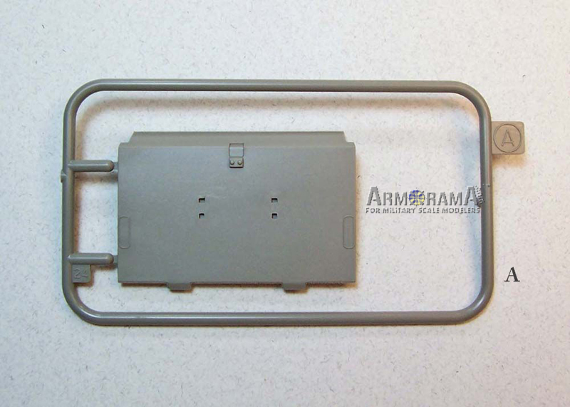
This is a new molding adopted from the previously released DML PzKpfw VI Tiger (P), Bergepanzer Tiger (P), Ferdinand and Elefant kits as it shares the same horizontal bottom plate, suspension mounting locations and hardware, mud scraping bracket attachments, access plates, rivet, bolt and drain plug details. The integrally molded lower angled bow plate and side pannier plates are new to this hull. The side armor plates have the necessary front and rear extensions for fitting of the upper hull and towing hooks up front. However, according to the only original side view drawing available of the VK45.02 (P), Cyber Hobby chose to extend the rear lower hull side armor plates further than depicted on the drawing. The armor extension plates integrally cutout with the lower hull vertical plates, as seen on the Tiger (P), Bergepanzer Tiger (P), Ferdinand and Elefant, to protect the drive wheel housings now extend the full height distance to the upper hulls angled rear deck plate. This would make good sense from the viewpoint of ease of manufacture and adding some additional interior space but with the penalty of an increase in weight.
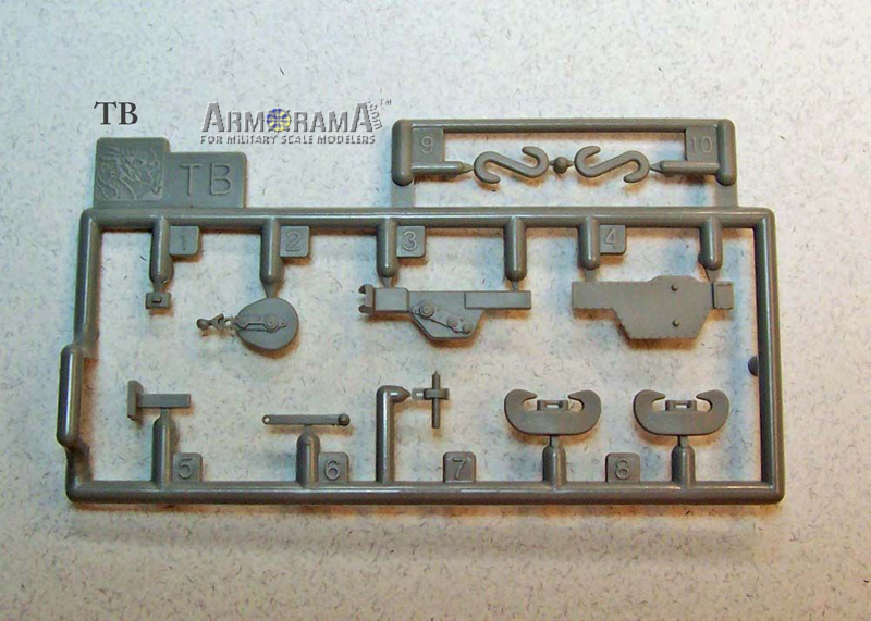
The one piece hull with its armor plate interlocking joints, weld beads and already mentioned lower plate items are realistically rendered and detailed via the slide-mold technology Cyber-Hobby and Dragon has come to be known for. The rear armor plate is a separate part and comes molded with interlocked armor plate joint detail with part of the towing pintle. This plate is to be fitted with the other half of the towing pintle, tow eyes, tow hooks, jack block, U shaped tow clevises and a multi-part highly detailed 20-ton jack along with its mounting brackets.
Missing on the rear armor plate is the rear reflector. The tail lamp (S1) is shaded as not for use, youll have to scrounge up both a fixture for the lamp and reflector from your spares box, as these items are not included in any of the sprue trees. These were part of the active and none active lighting system found on German tanks and should be taken into consideration.
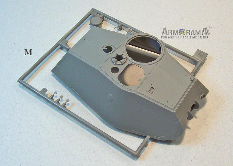
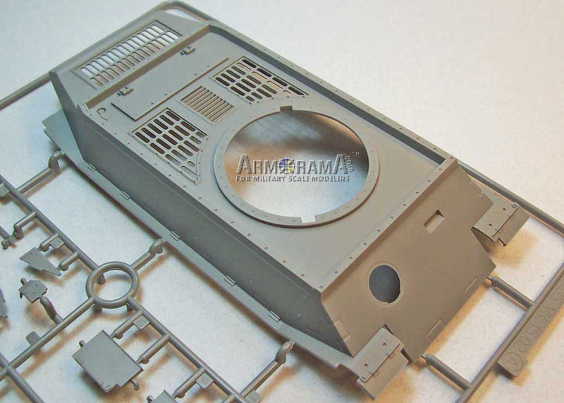
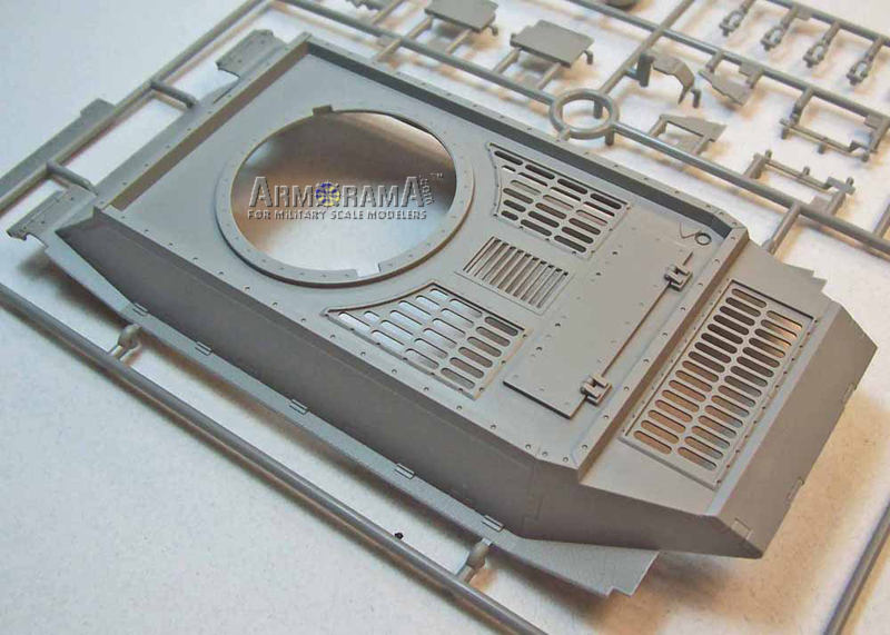
Upper Hull (Superstructure):
The upper hull is a large single piece slide molded new part that comes detailed with interlocked angled armor side, rear and glacis plates, weld seams, integrally molded track guards with front fenders and hinge detail, front, side and rear armor shot deflecting rails on the edges of the roof plate (to provide protection for the turret ring), turret ring race, opened ventilation louvers, engine access hatch, antenna rod mount with an electrical connection cover plate for the antenna, and cutout for the Kugelblende (machine gun ball mount).
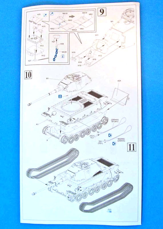
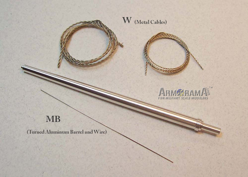
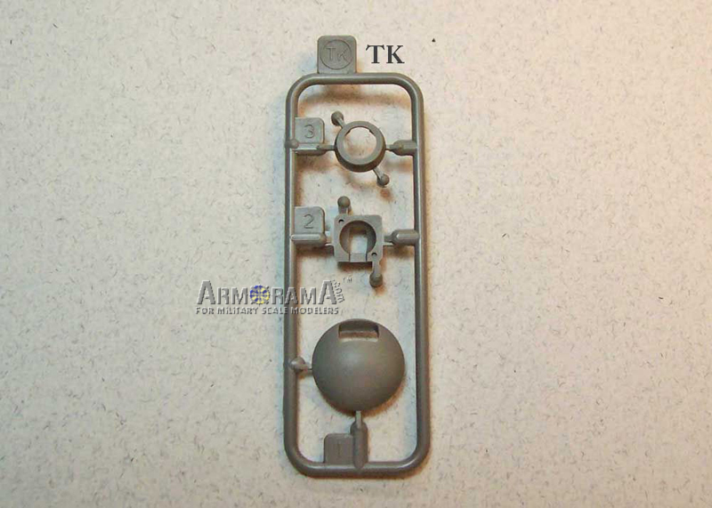
To this single piece upper hull youll be adding to the glacis plate a multi-piece MG 34 machine gun with its armored ball mount, drivers periscope view port, two front fender support braces with the fender retainer springs. To the hull deck are three supplied photo-etched grill screens with frames to be fitted to the three largest opened ventilation louvers and styrene handles for the engine access hatch. To both angled hull side plates youll be adding photo-etched towing cable brackets. An option, for both sides, is given for two types of braided metal tow cables with the respective styrene tow cable ends. A length of 240mm (9.44) is given in the instructions for each of the tow cables and that would include the affixed tow cable ends.
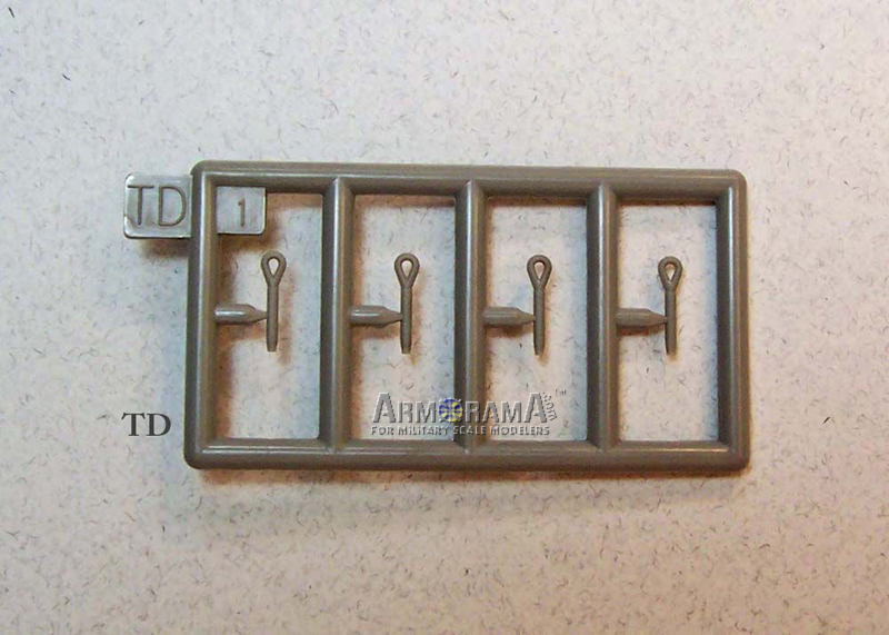
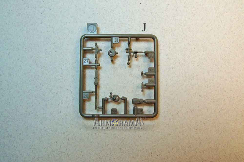
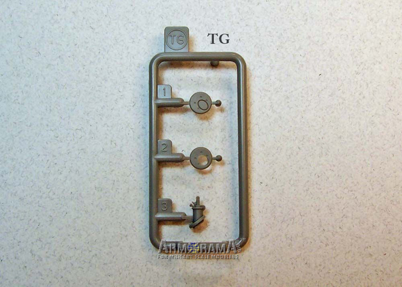
The instructions will have you mount tools only to the right (starboard) side of the vehicle. These include the wire cutters, sledgehammer, long pry bar, axe and shovel with each of them requiring you to assemble a three part supplied photo-etched tool clamp and support fixtures where appropriate for the tools. There is a multi-part Bosch night driving lamp set with the associated brackets to affix to each forward most section of the angled side plates. A pair of triangle shaped armor plates with interlocking detail will need to be fitted to the bottom underside of the rear hull. Finally, a separate set of rear fenders with hinge details and retaining springs along with a pair of fender supports finish off the upper hull.
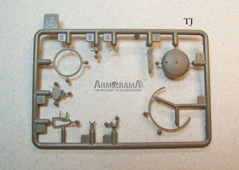
What are not mentioned on the instructions are the two small grab handles (parts E29) that should be fitted to both ends of the small center ventilation grill on the rear deck. These are shown on the assembly instruction line drawings in step 3 but no part numbers are given as they are shaded on the instructions as not for use. Also there are no parts for the antenna base or 2 meter stab antenna. An armored exhaust dome fan cover could also have been provided in the kit to be fixed at the corner by the radio operators roof to help vent residual smoke from the MG 34. This item being very needed and installed to all medium and heavy German tanks. The kit provides you with no less than three fire extinguishers but none are shown on any of the assembly instruction steps and all are shaded on the instructions as not for use. You should consider at least mounting one of these fire extinguishers on the vehicle as these were utilized on every German tank and usually mounted somewhere on the engine hull deck on the medium and heavy tanks. I would go with part TA6 for an end of war vehicle. Surprisingly a sprue tree of clear parts, lettered with an L, is provided in the kit box for adding a lens (L8) to the inside of each of the Bosch lamps but this sprue tree is not to be found anywhere on the instructions. But wait, theres more! A sprue tree lettered TL is also found in the kit box with armored exhaust covers and this too is also not found anywhere on the instructions. These covers are not needed as the vehicle was designed with the exhaust system housed inside the rear compartment and venting through the upper hull rear deck grating.
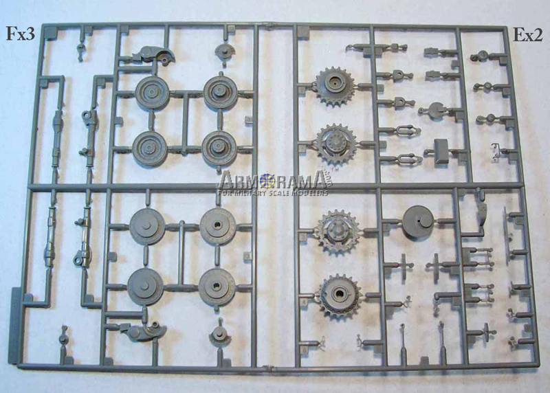
Suspension:
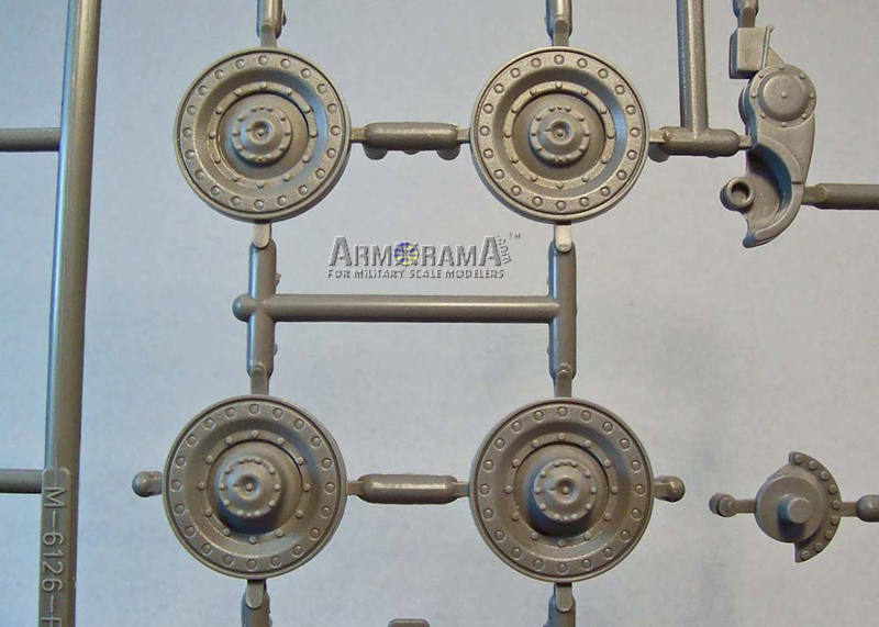
These are the same Porsche designed suspension components that are included in the DML PzKpfw VI Tiger (P), Bergepanzer Tiger (P), Ferdinand and Elefant kits. Each of the six externally mounted longitudinally torsion bar suspension arms are made up of five highly detailed pieces. Be careful when assembling these as there are four forward and two rearward facing suspension arm sets. The accurately detailed 700 mm metal road wheels come molded in four separate castings to be paired up with one set having an inner center hub and another having an outer center hub representing both types of paired wheel arrangements. Once all of these very well detailed pieces are assembled at three bogie suspension assemblies per side they will articulate making the model extremely suitable for placing it on an uneven ground diorama setting.
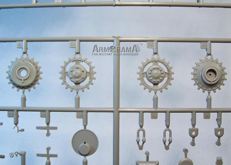
Both the drive and idler sprocket wheels are made up of three separate finely detailed pieces. The forward idler wheels are adjustable giving the modeler the choice of using an aftermarket individual track link set or the supplied kit tracks, which helps in both adjusting for track sag or when having one too many or too few track links. The instructions are not clear about the assembly sequence but the rear mud scrapers (A31 and A32) should be attached later or youll have a difficult time in fitting the rear drive wheels to the armored electrical motor housings.
Tracks:
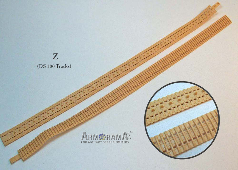
Two single-piece supple DS100 flexible styrene track lengths represent the later double link 640mm wide Kgs 62/640/130 tracks with ice cleats introduced for use on the Elefant and later used on the Tiger P. These tracks were a redesign from the earlier 62/640/130 tracks without ice cleats designed for the Tiger P and later used on the Ferdinand and Bergepanzer. The redesigned track set with the ice cleats, as offered in this kit, would be the correct choice for an end of war vehicle. The DS100 styrene tracks are suitable for use with most styrene cements and can be glued directly to the appropriate road wheel pairs to better represent the track sag.
An overlooked detail with all of the available kits concerning these tracks, with or without ice cleats, is that these tracks where fitted to the real vehicles with 109 links per side, the single exception being a Jagdtiger fitted with these tracks using the Porsche Laufwerk suspension, now at the Bovington Museum. The distance from the front idler wheel to the rear drive wheels remained the same for all vehicles sharing the same lower chassis and using these tracks. Because of the odd number of links two horn links were joined together on each track run. This can be seen on every preserved museum vehicle around the world that used either of these tracks and are seen in some WWII photographs. If youre a stickler for accuracy and want to show this detail somewhere on the track run then it would be much easier to obtain this feature by using an aftermarket individual track link set.
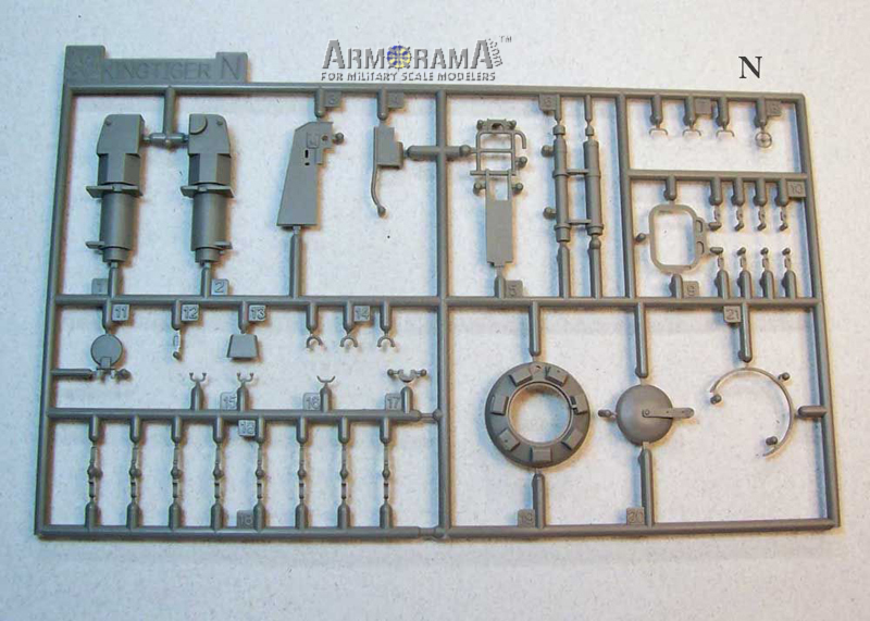
Turret:
This is the same turret designed by Krupp for the Porsche VK45.02 (P) as previously released with the Cyber-Hobby Initial production Tiger II and DML Premium Edition Tiger II kits. The turret body is a one-piece slide mold affair complete with the compound curved front plate, openings for the main gun, stepped apertures for both the gunners binocular gun sight and coaxial MG34, commanders cupola, loaders hatch, Nahverteidigungswaffe (close defense weapon), fan vent, shell ejector port hatch and rear escape hatch. The external details include the two curved armor guards on the front plate that reside behind the main gun mantlet (for providing protection against hits from the side), interlock armor plate detail, turret roof plates, weld seams, recess for the loaders periscope, block on the left front corner of the turret roof for the Zielstachel (forward blade sight), square splash guard over front armor plate, rain channels over the ports for the binocular gun sight, coaxial MG34 and shell ejector hatch opening. The right (starboard) side MP-Stopfen (pistol port plug) and finally the drain channel cutout on the right (starboard) side of the loaders hatch.
A deficiency with all of the kits provided with this turret is a weld seam molded around the base of the commanders cupola fixing it to the horizontal center roof plate that should not be there. Only on the Serien-Turm (series turret) for the Tiger II were the commanders cupolas, at some point during series production, welded to the turret roof. The turrets angled forward and rear roof plates as originally produced were fabricated from 25mm thick plating leaving a 15mm step up to the center 40mm roof plate. Except for the prototype vehicles, V1 V3, the kit turret body has the later 40mm plates that were later fitted to these turrets for use on the Tiger II. However, for an end of war vehicle both these issues are plausible.
There are raised outline location guides provided on both sides of the turret body for hangers to accommodate the Ersatzkettenglieder (spare track links) and these should be removed as there are no spare track links or hangers provided in the kit for the double link 640mm wide tracks.
To the top of the turret body you will add the commanders cupola of which you have an option of two separate cupolas to choose from. Here slide-molds were used to correctly angle the armored periscope guards against the cupola casting. One cupola is provided with and the other without rain channels cut into it. For an end of war vehicle I would go with the cupola having the rain channels. Seven clear periscopes are provided for the cupola along with an azimuth indicator ring. A separate casting to protect the hatch pivoting arm, three-piece pivoting arm with cupola hatch cover, anti-aircraft machine gun rail ring and two photo-etched parts; one for the commanders forward periscope guard rear sight rods and the other for the hatch cover stop, although unclear on the instruction sheet this would give the modeler the option of replacing the molded on thicker hatch stop with the more to scale thickness brass one, all of this together completes the cupola assembly.
The loaders periscope N12 is uncalled for in the instructions and there is also an unused clear periscope provided in the kit that could also be used provided the modeler opens the recessed area for the periscope, both these parts are shaded as not for use. You can then add the armored periscope guard, shell ejector hatch cover, base flange for the loaders hatch, ventilation fan water tight seal cover with handgrip but no part is provided for the fan armor guard should the modeler wish to display the vehicle combat ready where the water tight seal cover would have been stored inside. For an end of war vehicle you could add the three separate Pilze sockets for the 2-ton Jib Boom. Optional parts are provided for the three-piece Nahverteidigungswaffe (close defense weapon) giving the modeler the choice of displaying this weapon with the port in the open or closed position and for rotating it into any desirable position on the turret roof. Rounding out the turrets roof items is the early 15mm loaders hatch. Here the modeler has the option of fixing the hatch in the open or closed position with separate hatch cover and pivoting arm parts provided to detail the inside of the hatch and turret should the modeler decide to position the hatch in the open position. The hatch grab handles N7 are not shown in the instructions and are also shaded, as not for use, dimples are provided on the hatch and one of these should be fitted to the outside of the hatch and another one to the inside. There is a curved section of armor plate that houses the left side pistol port armor plug that will need to be fitted to the left side of the turret with the resulting seam around the plate needing to be filled.
At the rear of the turret is the armor frame with the protruding conical bolt heads that houses the rear turret hatch (shaded as not for use on the assembly drawings, ignore this and use this part), hatch torsion bars and torsion bar armor guards. Here again the modeler has the option of displaying the rear hatch in the open position. Separate parts that represent the hatches interior panel, hatch locks, pistol port armor plug with chain loop and slide guard are provided. The kit also provides the modeler the option of a workable four-part photo-etched slide guard with a metal rod for keeping all the hinged sections of the parts together. The rear hatch grab handles N15 are not shown in the instructions and are also shaded, as not for use, location holes are provided on the hatch parts and these should be fitted to the top outside and top inside of the hatch.
A long length of photo-etched brass chain is provided for the rear hatch pistol ports armored plug should the modeler chose to show the plug hanging open with the hatch closed or fixed to the hatch with the hatch in the open position. The instructions show where the chain is to be attached on the armor plugs chain loop but not where the other end of the chain is installed on the kit? The other end of the chain should be fixed to the interior hatch panels detailed raised circular collar. On the real vehicles that used this same rear hatch there were two chains installed to the same locations with one being shorter for allowing the plug to hang away from the opening and the longer chain for pulling the plug back into place. If the modeler desires, there is enough brass chain length provided on the photo-etch fret to add this detail.
The turret bottom panels and bearing ring housing is molded as a single piece. What is surprising is that the instructions do not show the necessary parts that need to be installed to this part, before installing it to the turret body, that enable the modeler to fit the main gun to the turret and these parts are included in the kit but are shaded as not for use. For the first time modeler parts H3 and H4 would need to be assembled together first. Then fix part H21 to the slot on H3. Attach, but do not cement H6 on the right side of H3 (slot side) and H5 to the left side. Now fix this assembly to the turret bottom H22. H5 and H6 will only fit to each of their own corresponding slots. Parts N1 N6 are provided in the kit should the modeler wish to assemble the main guns breach and housing but these parts are also not mentioned on the assembly instructions and are shaded as not for use.
Main Gun:
The kit provides you with an option to build one of three 8.8cm L/71 main gun barrel types. The first two are of the mono-bloc 8.8 cm Kw.K. 43/2 L/71 type with one a molded two-piece part with an integrally molded early weighty muzzle brake and the other a turned aluminum piece with a separately molded three part late lighter and smaller muzzle brake. The third option is a molded two-piece sectional 8.8 cm KwK. 43/3 L/71 type with an integrally molded early muzzle brake. Any of these barrel options can be attached to the three-piece mantle.
Color and Markings:
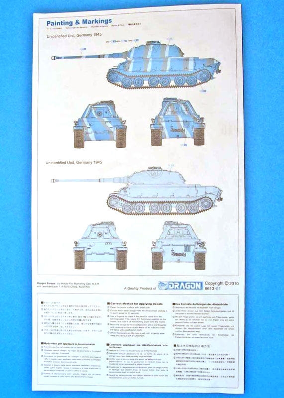
There are two color schemes provided on the Painting & Markings page and both are for hypothetical end of war vehicles. The first of these is for a red oxide primer coated vehicle with paired angled stripes of Dunkelgelb and Olivgrün. A paint mixing ratio guide is given for the red brown oxide primer base coat. The second scheme is for an overall Dunkelgelb vehicle. A color chart is provided on the second page of the assembly instructions and is keyed for hobby paints from both Gunze and Testors.
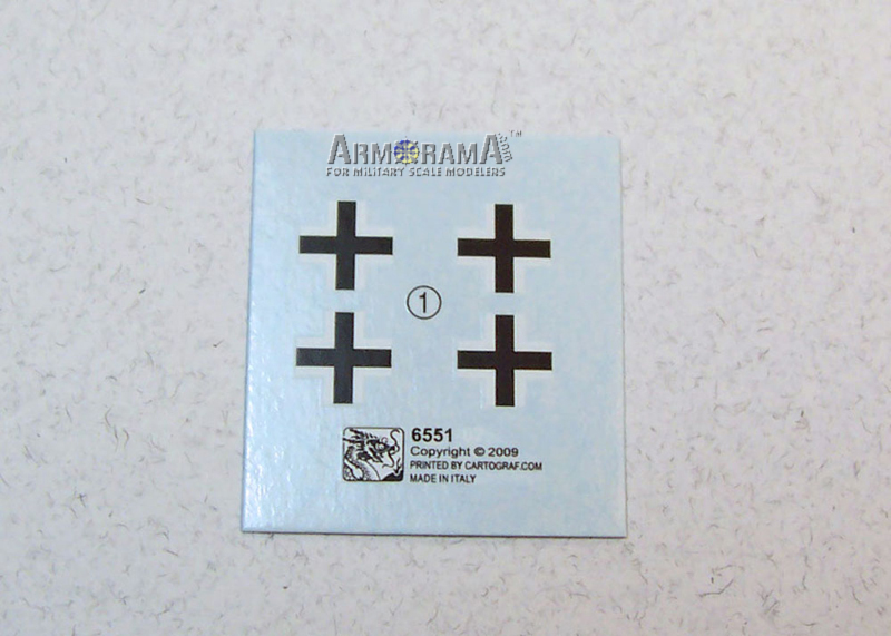
A small sheet of matt film water-slide decals from Cartograf provide four small black and white Balkenkreuze insignias that are in register but no placement for where the decals are placed on the vehicle are given in the instructions.
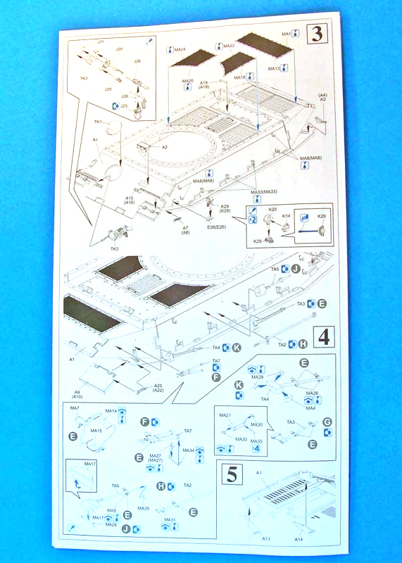
Assembly Instructions:
The kit comes with a six-page instruction sheet filled with diagram line drawings, assembly steps and color and markings guide to assist the modeler in completing the unassembled model. The assembly instructions are spread out over four pages encompassing 11 steps with all but the last two steps containing their own separate detailed sub-assembly information for the various components. The line drawings are very well detailed and clear and should not be a problem for the experienced modeler to follow, however the instructions fall short in that no sequence steps are provided for which parts to put together first to avoid an assembly mishap (removing an already fixed part to fit a part that should have been added before). And many items being left out of the assembly instructions and shaded as not for use that should have been included in the assembly steps.
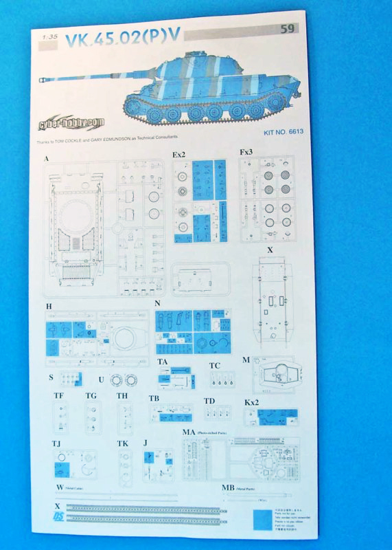
Two more pages complete the instructions and these include the Painting & Markings page giving the modeler detailed three view side drawings of the vehicle as an aid in painting the color schemes. The other page encompasses a fully detailed overhead line drawing view of each of the separate lettered sprue trees with the individual kit parts marked with their corresponding part number, with the unused parts shaded as not for use. This page helps the modeler to identify each of the parts as called out for on the assembly instructions.
Conclusion
Except for the original preserved documents and few pencil line drawings the VK45.02 (P) could easily be considered a paper panzer, as there is very little documented history and no known photographs of this vehicle to date. The kits chassis and suspension basically match the few available line drawings found on the cited references below. With the exception of the turret that was later adopted over for use on the initial and early production Tiger II series program, and well documented with plenty of photographs, these drawings are of limited use to only the first produced and cancelled VK45.01 (P2), typ 180 vehicles. For instance the upper chassis deck details and fenders are conjectural for the most part but strike a good balance with what was available at the time these three vehicles, on the second contract, were produced. This is an important vehicle in the development evolution of the most feared tracked axis land weapon in the world during WWII the legendary Tiger II combined with its well trained crews.
The kit appears simple enough to assemble for anyone with some moderate modeling skills and experience. This should appeal to anyone wishing to produce a conjectural end of war vehicle as well as for those seeking to model a historically accurate vehicle this will serve as a good base. And for those collecting all WWII German armor or just the heavy tanks this release should not be missed.
References used for this review:
Germanys Tiger Tanks, VK45.02 to Tiger II; Schiffer, by Thomas L., Jentz & Hilary L., Dolye
Paper Panzers; Panzer Tracks No. 20-1; by Thomas L., Jentz & Hilary L., Dolye
A review of the Voyager upgrade set for this kit can be found
Here on Armorama


Comments