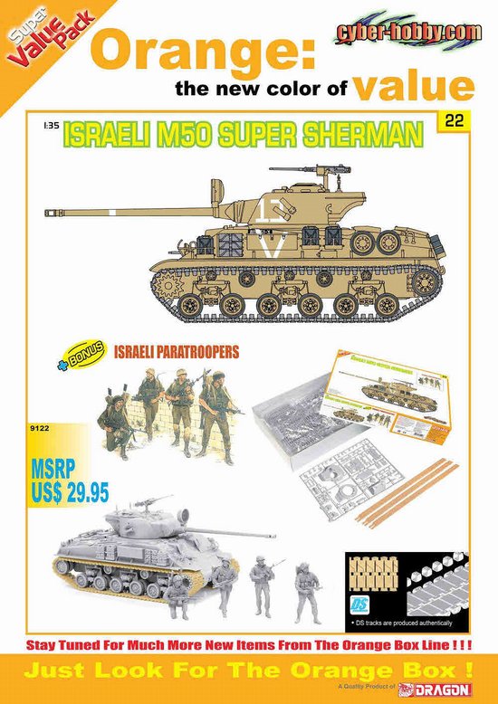
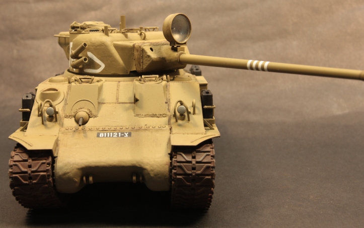
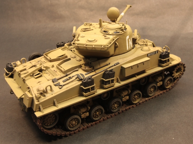
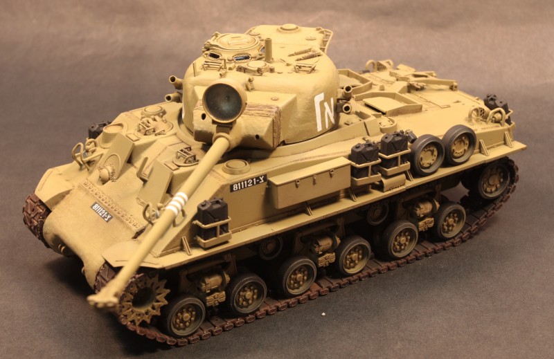
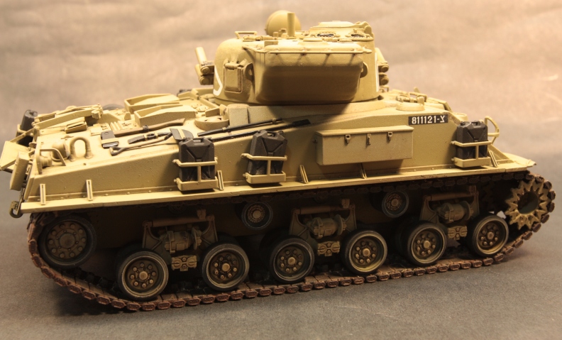
When WWII ended, who would have thought that the venerable US M4 Sherman would continue to soldier on well into the 1970s? That is exactly what happened as Israel acquired and began modifying them for use as their own; finding the first few in an Italian scrap yard immediately after the war ended. From this initial purchase of 35, only 14 were made operational, but it set the wheels in motion for what was to come. By 1964, Israel had converted approximately 300 Shermans into the M50 version, equipping it with the French 75mm CN 75-50 main gun, HVSS suspension and a U.S. Cummins V8 diesel engine. Many other modifications would come later.
The M50 saw combat in several of the conflicts in the region, including the Six-Day War in 1967, and the Yom Kippur War in 1973. For a tank that was over 40 years old, it was holding its own against newer tanks such as the Soviet T-54/55 and T-62, its crewman upholding the motto of the Armor Corp: Man is the Steel!
Overall, the Sherman has seen more modifications and has had more sub variants produced than any tank in the Israeli Defense Force (IDF) inventory: everything from an SPG to an anti-radar missile launching platform to a medical evacuation vehicle. To say the IDF has gotten their use out of this stalwart war horse would be an understatement.
I was happy to see Cyberhobby/Dragon release this particular kit, as I have a liking for IDF armor. Having built one of these kits in a previous version, I was curious to see if there were any changes made from the older offering. Sadly, not much was changed, other than the inclusion of the DS tracks, some added weld detail on the hull, and the inclusion of figures.
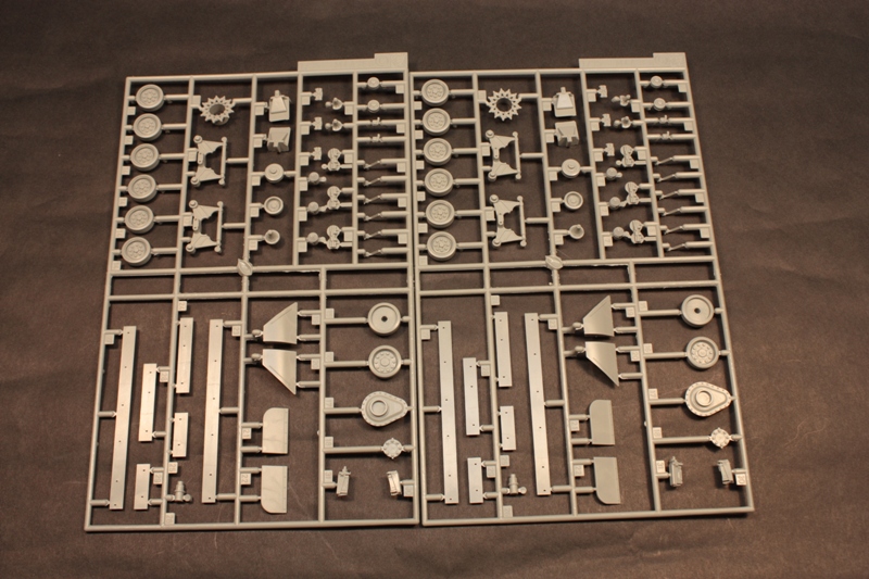
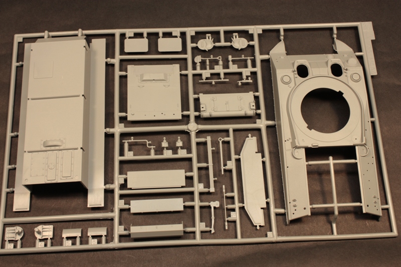
The box lists the parts count at 380, but I dont know if that takes into account the figures or not. What you get on the 21 light gray sprues are some exceptionally well-molded parts. There are two A sprues with one being larger than the other and containing the upper hull, lower hull and a few of the smaller parts for the upper hull such as the drivers and bow gunners hatches. Most of the smaller A sprue is not used, but contains additional hatches, final drive housings and a host of other parts.
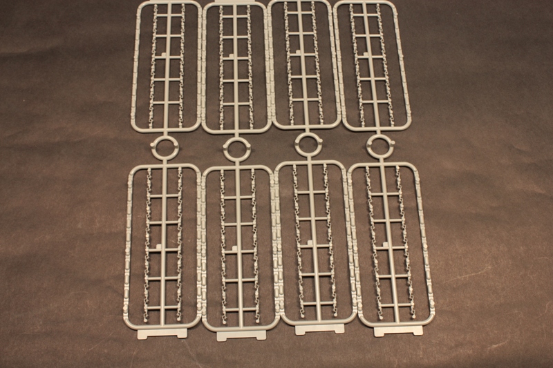
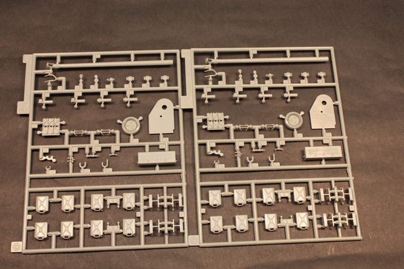
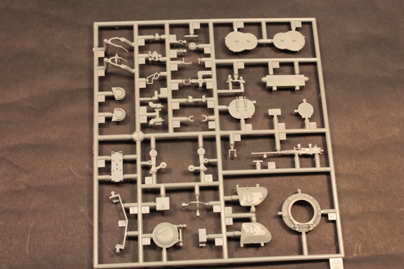
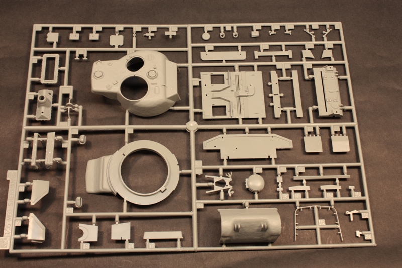
What is on this sprue is the TC cupola and hatch along with the loaders hatch and .50 caliber MG. There are three lengths of DS tracks included that are needed to make the longer length tracks for the M50. There are six differing sprues for C labeled parts: two contain the majority of the suspension components; the others, the hull length fenders, their corresponding supports and some front fenders that arent used. Sprue B contains the majority of the turret components, along with the back deck pieces. The main gun is split between 2 F sprues, which also house the transmission supports to mate the transmission to the lower hull. The 2 G sprues contain the jerry can racks and the cans themselves. The 8 T sprues have all the center guides for the tracks.
Extra parts remaining included a different style back deck, rear plate for the upper hull, lower hull engine access doors, storage bins, what appears to be a different exhaust, additional armor scabs for the hull sides, different style fenders, additional lengths of fender skirts, suspension bogies, support roller arms, jerry can racks, light guards, hatches and other assorted parts I could not ID. There is also a small piece remaining on the PE fret that I could not figure out, although it looks to be some sort of small arms ammo rack.
the build
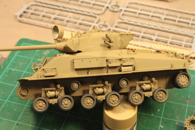
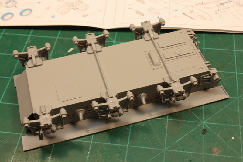
Despite the disappointment, I pressed on with the build none-the-less. Construction began with the suspension parts. A minor bit of surgery is needed on 6 of the parts labeled C6. These are the mounting points for the HVSS suspension bogies, and its a very small contact area here, so lots of patience is prudent when fitting them.
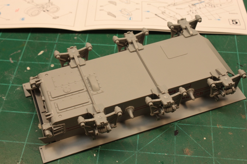
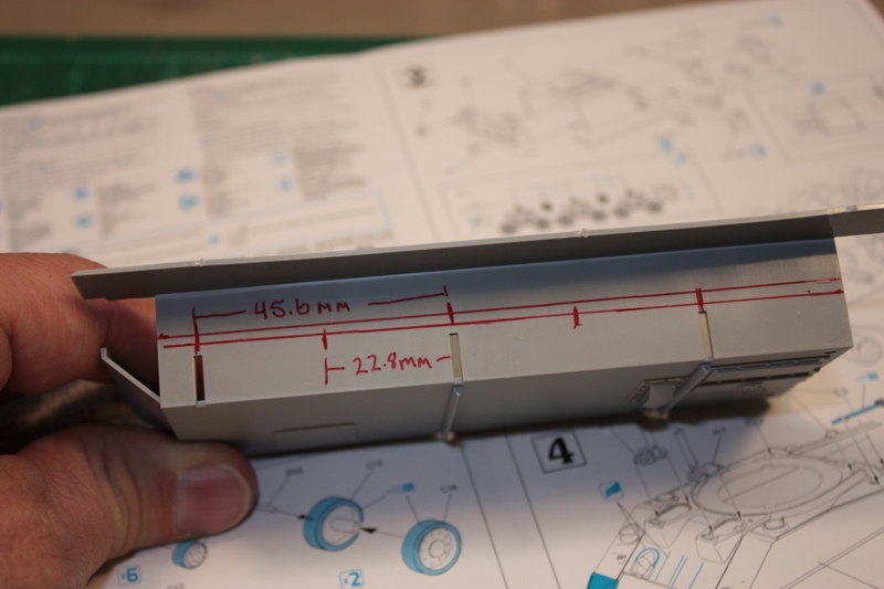
In step two, dimensions are provided for installing the return roller supports, the suspension mounting plates and the rear hull piece. The smaller of the return rollers can be installed without using any markings, as they sit directly over the bogies and can be put on after the mounting plates have been installed. Part C8 will require that one of the mounting pins be removed for it to sit flush with the bottom of the hull. You can see which pin was removed in the pictures. The instructions also call for removing a small amount of plastic from the bottom of the hull for the rear-most and middle bogie mounting plates to properly fit. I cut approximately 1mm off each end. The instructions show pretty clearly what needs to be cut.
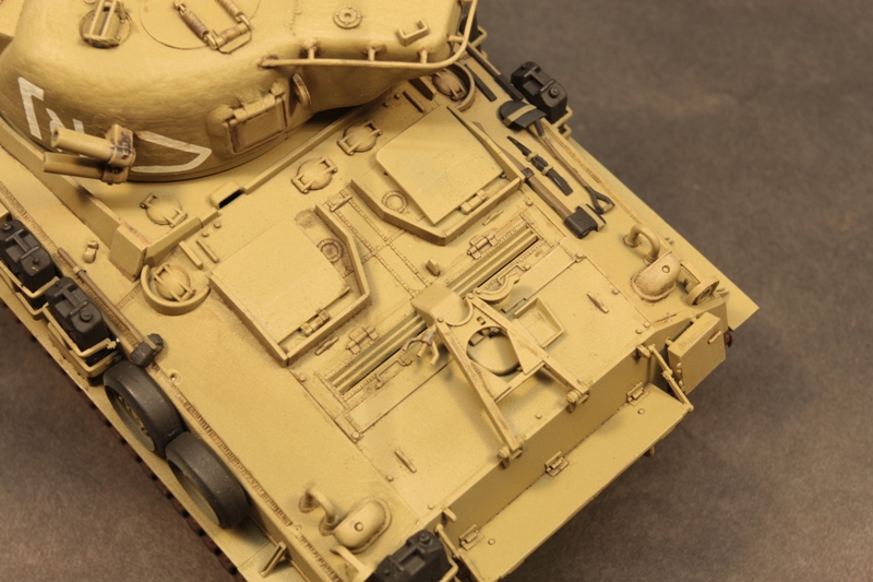
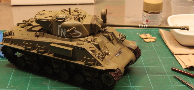
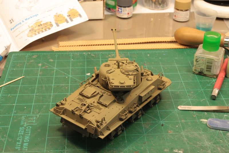
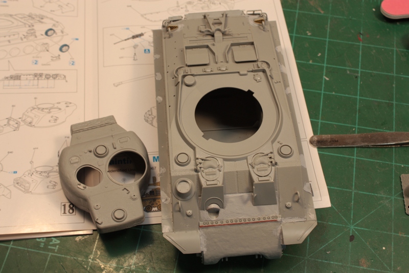
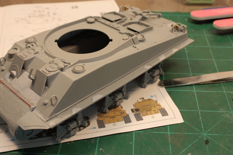
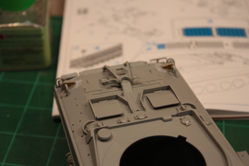
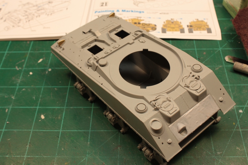
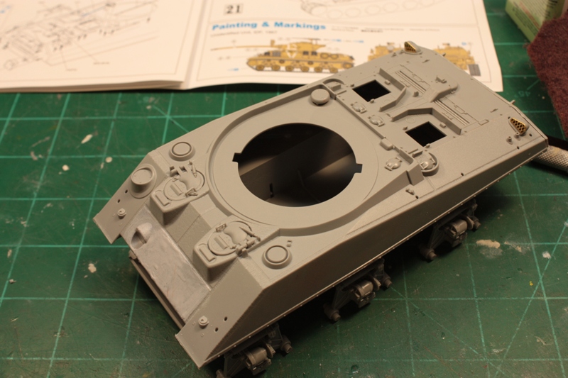
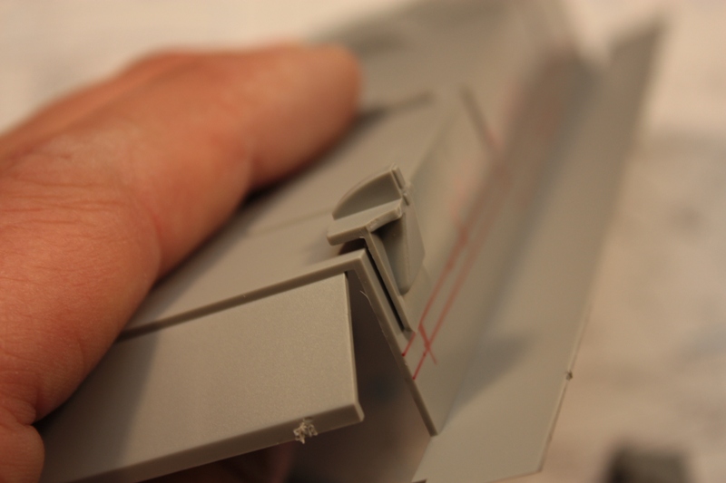
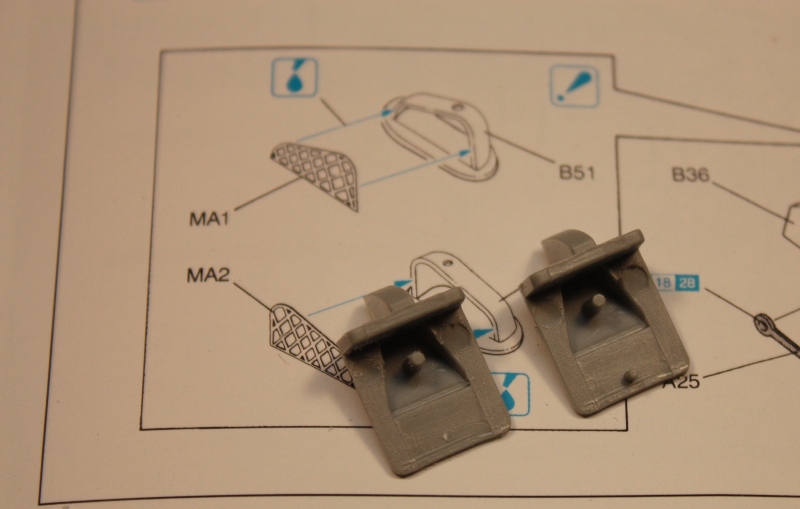
The lower hull is pretty much completed by the end of step #3, so we move onto to the upper hull. The molded-on fenders are removed in step #4, and a few of the assorted pieces are added to the upper hull. PE screens are provided for the small intakes on either side of the rear hull, and they fit very well. The back deck is added here, and it fits perfectly with not a gap to be found. Next are the pioneer tools, but I left mine off until final assembly. They are clunky-looking at best and would be better replaced with resin items or ones from the spares box.
Steps #6 -9 continues with the back deck and rear of the tank with its various boxes, covers, and plates. There are lots of holes in the upper hull area for the pioneer tools, and other parts, along with some random holes that have no business being here. These were found after final assembly and addition of the tools, so I filled them with white glue and painted over the results.
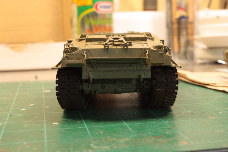
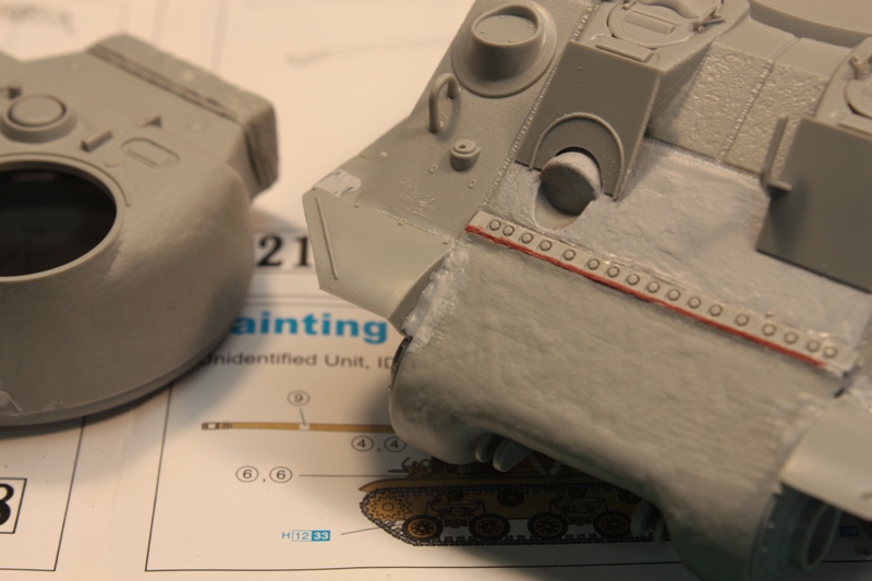
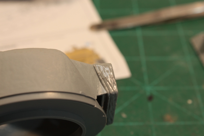
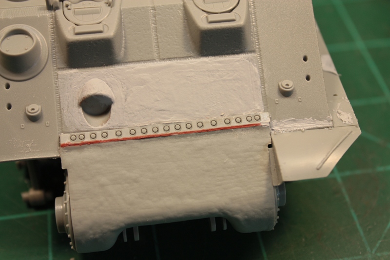
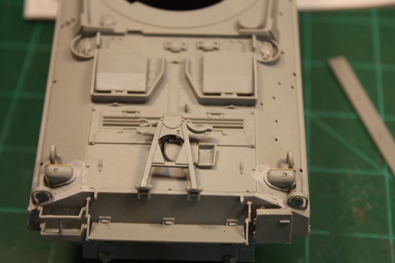
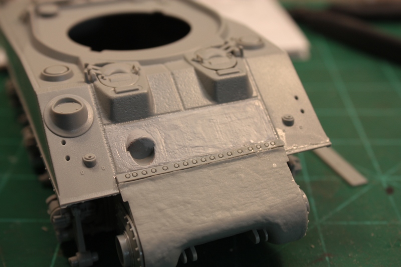
Steps #10-12 deal with mating the upper and lower hulls, adding the transmission cover and fenders to the sides of the tank; this is one area I ran into problems. Once the transmission cover was assembled, I dry-fit it to the upper and lower hull area where it was supposed to go. There was a huge gap between it and the bolts that would have held it in place on the real tank. It took some serious amounts of force, and colorful words, to get this gap closed and then nailed down with a healthy dose of CA glue. Once dry/cured, the smaller seam was filled with red putty and blended into the surrounding area.
The sprockets are added in step #12, but again, I left mine off until final assembly. This would prove to be a headache all its own later .
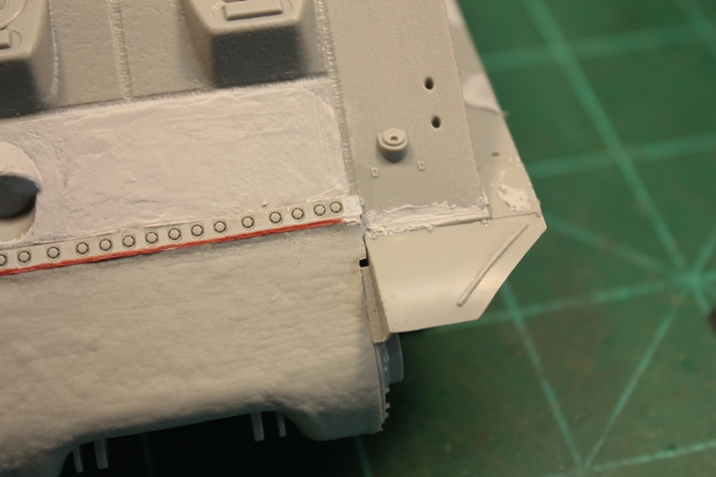
The side fenders installed easily enough, but there was some question as to where on the hull they mounted. There is a row of bolt heads that stick out, and I couldnt determine whether they went above or below said bolt heads. A quick check of my references showed them going below. That made installation easy, as I was able to use the bolt heads as a stopper for the fenders. I butted them up against the heads, touched a little Tamiya Super Thin to the seam, and they were on in no time. The angled supports were added after filling the unused mounting holes on the fenders with some thickened Mr. Surfacer 500. Only 6 mounting points are used on each fender. Checking my references and instructions helped here.
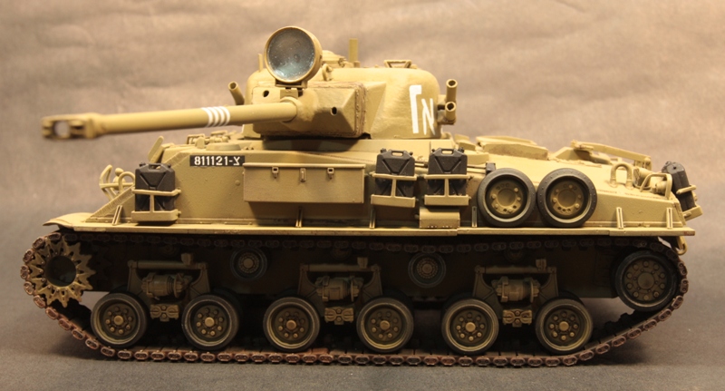
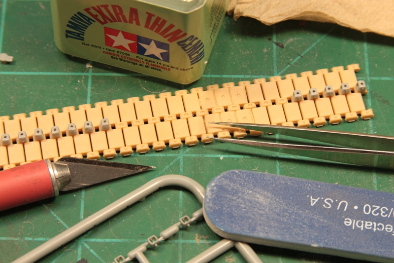
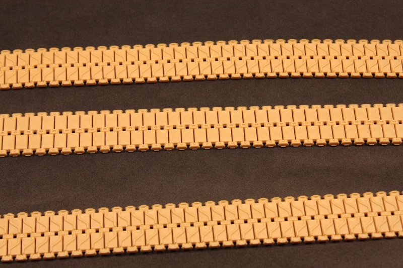
Step #13 deals with the tracks. Having never worked with DS tracks, I was pleasantly surprised at how easy they are to use. The kit provides three lengths of track to make up the two lengths of tracks for the tank. The instructions call for removing 2 runs each of 7 track blocks from the extra length of track provided, and adding those extra blocks to the other two lengths of track. As it turns out, I only needed three extra track blocks per side. It was easy enough to remove what was not needed using a new #11 blade. The tracks were painted and weathered separately, then installed at final assembly. Tamiya Super Thin cement again proved all that was needed to join the two ends. The most tedious aspect of assembling these tracks was having to add the center guides, which are provided as a separate piece
all 86 of them per side! This took the better part of 2 hours to do, but they look great.
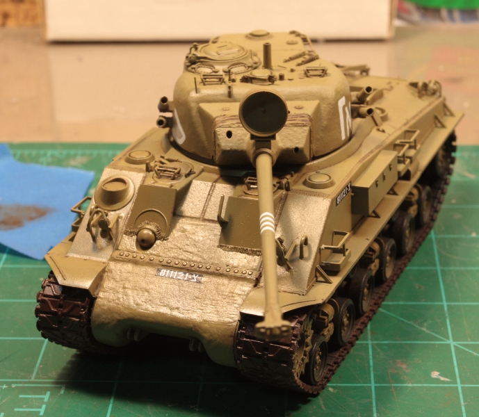
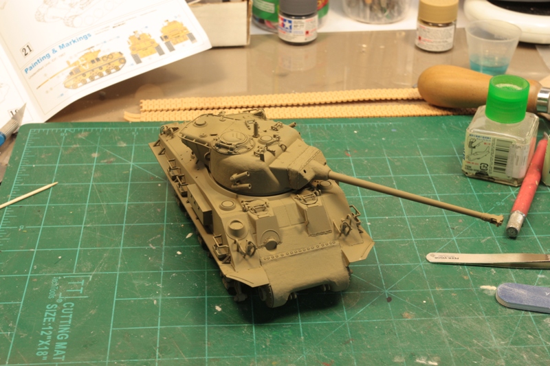
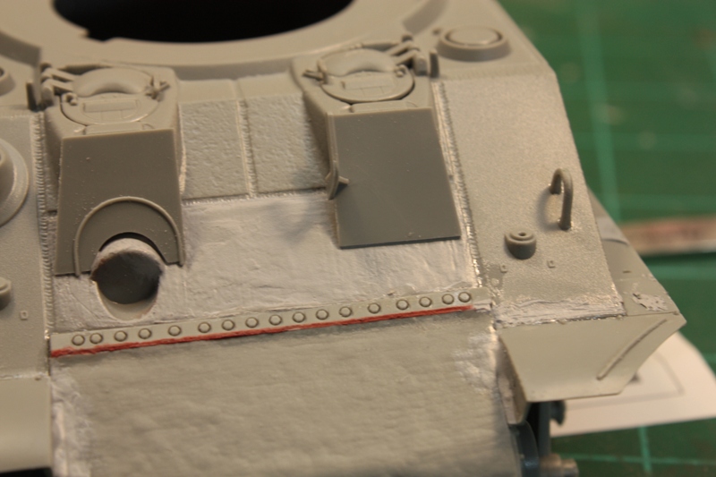
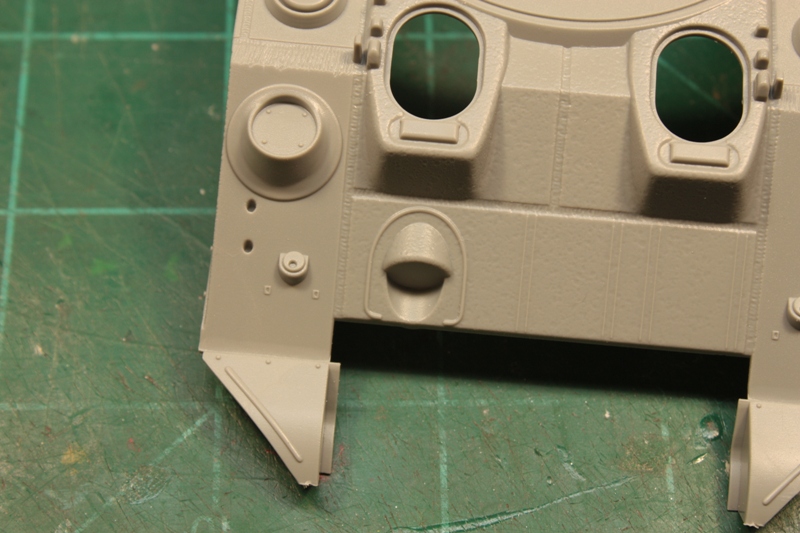
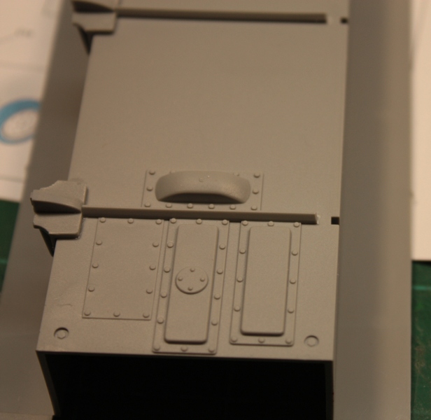
Steps #14-15 dealt with various items that go onto the sides of the upper hull, and there is lots of stuff to add. However, there is a diagram provided that shows the spacing of all these additions. It helps immensely to have a set of digital calipers on hand that can be set up for metric measurements. I installed everything called for here, except for the jerry cans, spare road wheels and spare track blocks. Those would come last, after painting was complete. I added the prominent weld beads along the bottom of the drivers, and bow gunners armor plates, as they were missing from the kit parts.
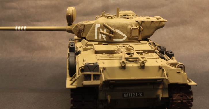
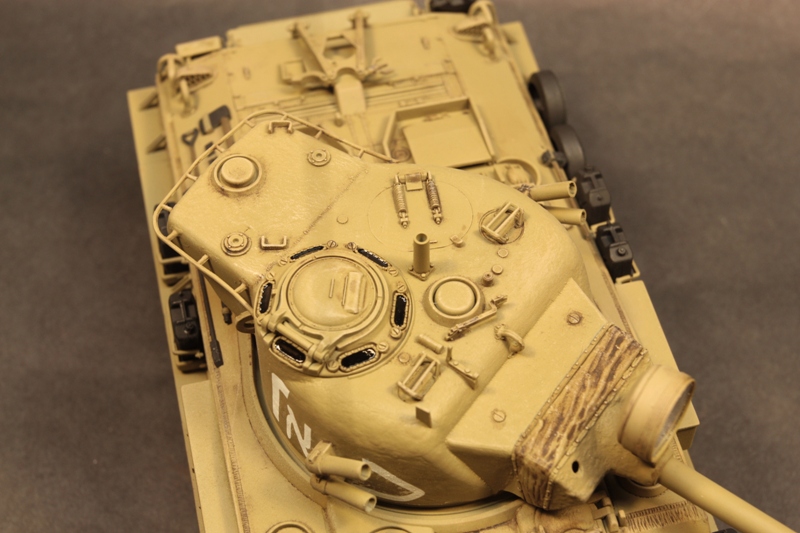
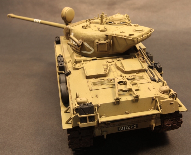
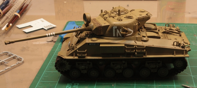
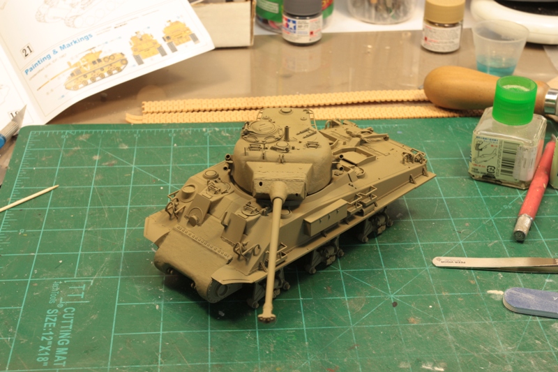
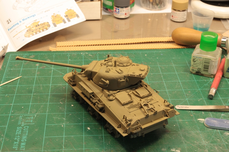
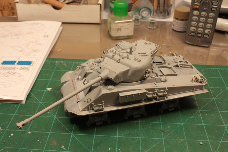
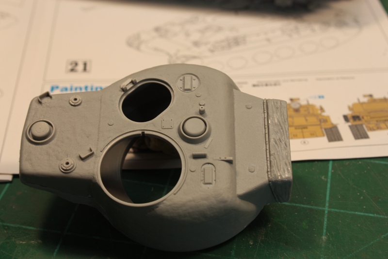
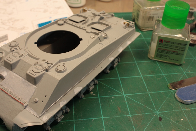
Steps #16-20 deal with the turret, and this was the most enjoyable part of my build. While pretty basic, the texture on the turret is really nice, as is the overall detail like the TC hatch, etc. A few PE pieces added here would really make this thing stand out even more.
In step #17, the mantlet cover is assembled from two pieces that end up leaving a nasty seam line on either side of it. This can be fixed using an oval or round file, then dressing the results with a few applications of liquid cement to smooth things out. The only drawback to the main gun is it cannot be elevated or depressed. Everything locks into place. Im sure with some epoxy putty, and some minor surgery, it could be freed, but not right out of the box.
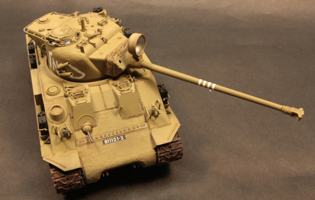
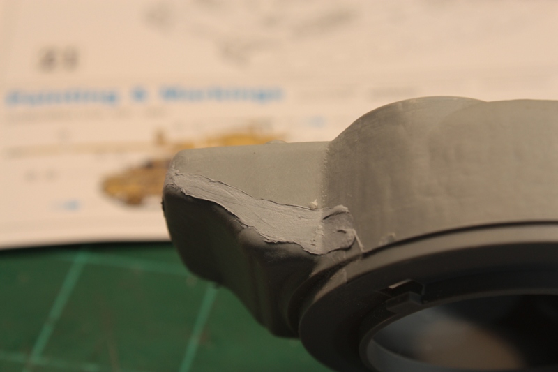
The smoke grenade launchers do not have a positive locating point on the turret so you will have to check your references. The same goes for the ammo/pistol port on the left rear of the turret. I used Magic Sculpt to blend this area into the rest of the turret, as it had a pronounced step to it. I left off the .50 cal MG as it looked clunky to my eye. The infantry rail that runs around the back of the turret also have no locating points, so again, check your references. I used small amounts of Mr. Surfacer to blend the ends of the rail attachment points into the turret.
Final assembly & Problems
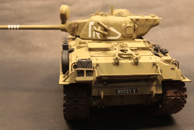
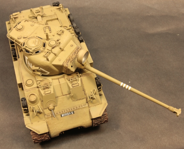
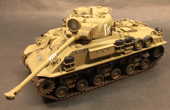
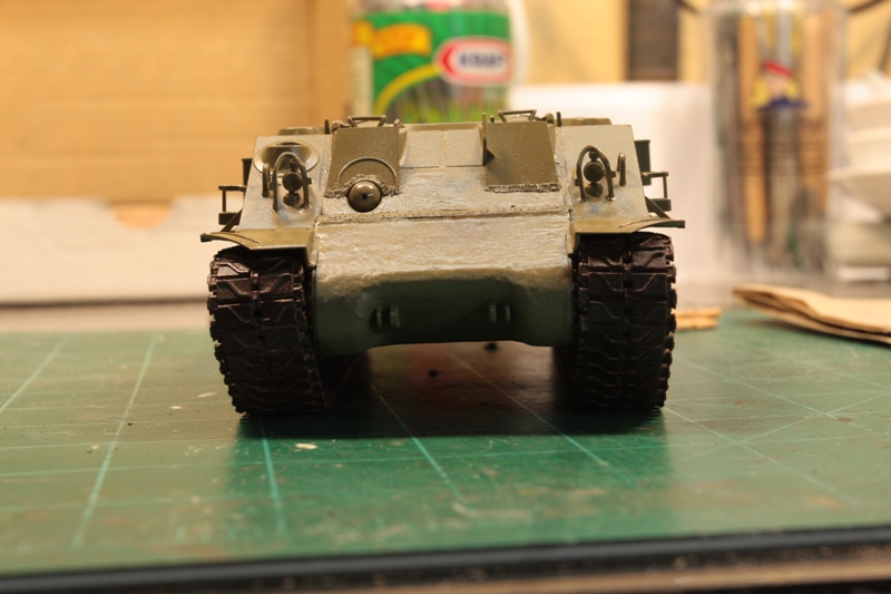
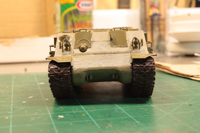
As I mentioned earlier, I left a lot of stuff off until final assembly. Some of this would prove to be no problem; others would be a royal pain in the behind. Beginning with the installation of the tracks, I ran into a fit problem, as they were too long (already noted above). I trimmed them and got them wrapped around the sprocket and idler wheel, then joined them on the bottom of the tank, where it would be less likely to be seen. I checked the alignment of the tracks, and was rewarded with a knock-kneed appearance. The sprockets stuck out past the road wheels, thereby creating a nice V effect when viewed from the front. And, the sprockets were pressed in as far as they would go against their mounts and the hull.
That leaves one option: move the road wheels out away from the hull some more. Not something that is easy, and unfortunately will not be happening. I dont recall having this problem with my older build, so I dont know where the problem lies. It looks the part when viewed in profile; just dont look at it head-on.
Coupled with this is a problem with the idler wheel mounts: step #3 calls for removing the mounting pin/peg on parts A3 and A4 that the idler would mount to. Supposedly the small pin, part B53, that is inserted into the back of the idlers is going to hold them on. Dont do it! I made the mistake of following the instructions, and ended-up using telescoping styrene tubing to replace the mounting pins I had removed.
Next on the list: the jerry cans do not fit into their mounts properly. The can themselves are too wide/deep. I had to pop one corner on all the mounts to get them to squeeze in, and couldnt fix the cans themselves as they were glued together from the get-go and already painted. To fix this issue, you will have to sand the can halves down and check them until they fit then glue the halves together and paint them as called-for. Since there is no power cable supplied for the search light, you will have to source that on your own. Not hard, but needed to look the part.
Now, not all is doom and gloom with this kit albeit more than I would like, but not horrible. And there is a ton of extra parts left over that will find a welcome home in the spare parts box. The decals are minimal and went down without too many problems. The figures included with the kit are old, even by Dragon standards, but do come with a good compliment of weapons. I would probably only use them as a basis for sculpting other figures; armatures if you will.
conclusion
While the addition of the DS tracks is a nice touch, I was hoping that the kit would have received the same amount of upgrading that the M51 kit did. Even with the shortcomings, this vehicle builds into a fair representation of the M50; just be prepared to do some work.
SUMMARY
Highs: Interesting subject, DS tracks, nice turret detail, extra parts, minimal decalsLows: Fit of sprockets/tracks, transmission cover fit finicky, minimal attachment points for suspension, no locating points for return rollers, smoke grenade tubes or ammo hatch. Unnecessary removal of mounting pin for idler wheels. Tracks too long.Verdict: Be prepared for some work. A rehash of an old kit. Still waiting on a new tool M50.
Our Thanks to Dragon USA! This item was provided by them for the purpose of having it reviewed on this KitMaker Network site. If you would like your kit, book, or product reviewed, please contact us.
Matt Have followed this I was a little surprised no one had taken the time to post here so here goes. Firstly thank you for doing this as a build review (I know what a pain it can be with the stopping and starting to take pictures). What was your opinion of the included figure set and their equipment? Do the barrels of the infantry and tank weapons need drilling? Having highlighted the issues with the kit and the big plus of the turret and MagiTracks which are very good buit too long would you buy it?
The figure set dates from 1990, so it is not exactly state of the art. Yes, the weapons need to be drilled out. Israeli vets I knew commented at the time the kit came out that the depiction of the squad machine gunner as also carrying the folding stretcher on his back was nonsensical--he would be overburdened, and a rifleman would ordinarily have that task.
Early 90's Dragon figures tended to be on the tall side, and the chests tended to be rather shallow. Dragon's sculpting is a lot better these days.
Thanks for the comments Darren. Gerald hit it on the head in regards to the figures and weapons. As to the kit, I wouldn't pay full retail for it simply based on the amount of work involved needed to fix the suspension issues. Hope that helps. "Q"
Thank you Matt and Gerald for answering my questions. I asked as I have seen this in UK model shops for £34 - £36 and thought it was a lot of money with the problems highlighted in the review.


Comments