Introduction
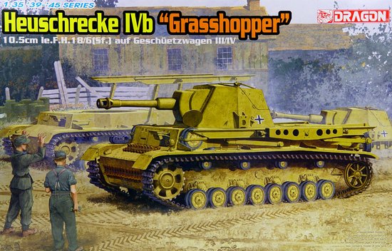
For the purposes of this review, I will refer to the vehicle as "Heuschrecke". I need to state this because just about every source has a different name for this. I'm pretty sure this vehicle is the 10.5cm leFH 18/1 L/28 auf Waffenträger Geschuetzwagen IVb and sources differ on whether this was a "Heuschrecke" or a "Heuschrecke 10". There is also some confusion between this vehicle and an earlier one where the earlier one did not have a rotating demountable turret and was built on a modified Panzer IV chassis with 6 Panzer III road wheels per side. I don't know if it used the Panzer III suspension or modified Panzer IV bogie units. Eight of those were made and were used by 16th Panzer Division in Russia. Ultimately it was decided to use the Panzer II chassis instead, which gave us the little "Wespe".
The subject of Dragon's kit was a weapons carrier based on a lengthened Panzer IV hull. It mounted a 105 mm gun in a turret along with a crane to unload the turret so it could be used as an artillery piece while the vehicle served to carry ammunition. This vehicle was intended to replace the "Wespe". 3 prototypes were made but it's not certain if any saw combat. I'm not certain why Dragon chose to model this rather than the earlier one that did see combat, perhaps it was because of the unusual ability to unload the turret. I do recall this vehicle being done in kit form many years ago, possibly by UPC. The name "Heuschrecke" means Grasshopper in German, no doubt referring to the folded crane looking like folded grasshopper hind legs.
Kit Contents
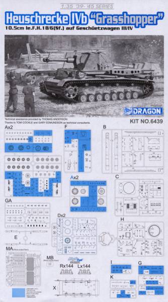
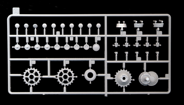
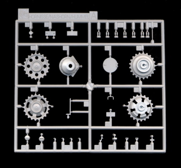
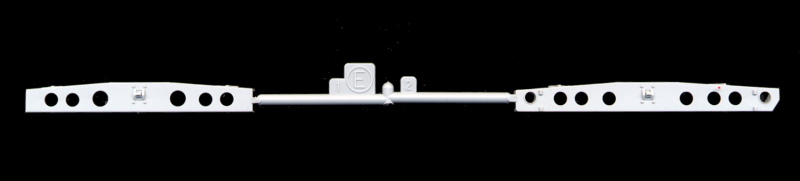
There is one big bag with the sprues specific for this kit and a bunch of sprues from other Dragon kits. This means you will need to be careful as there are 3 pairs of sprues labeled A. 2 pairs that were broken apart to fit in the box came from a Panzer IV kit while the the other pair comes from a Hummel/Nashorn kit. All of these hold suspension parts.
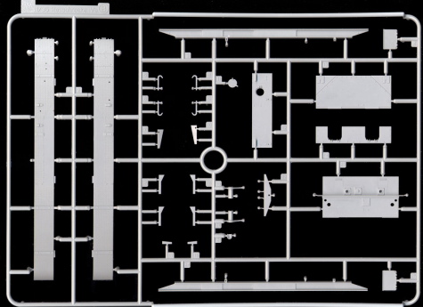
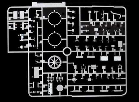
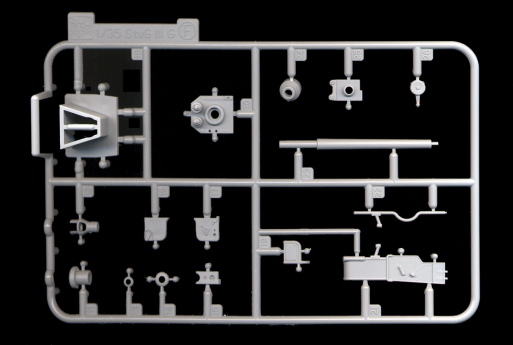
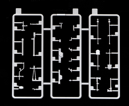
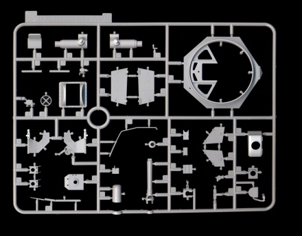
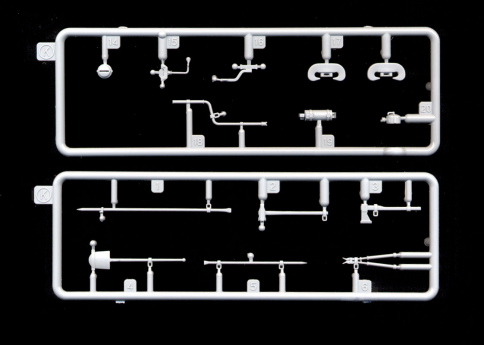
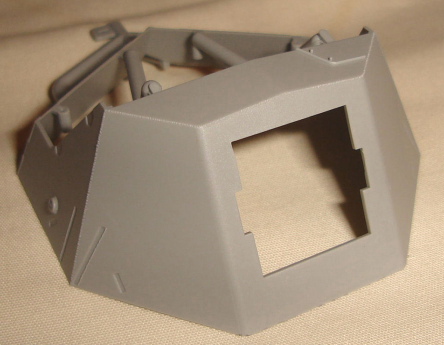
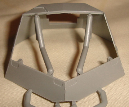
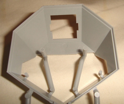
Sprues B to E are kit specific; B holding most of the crane parts, fenders, and some upper hull pieces; C holds the major pieces for the upper hull; the two D trees hold smaller detail parts for the hull and turret; E tree holds parts for the dismounted gun platform.
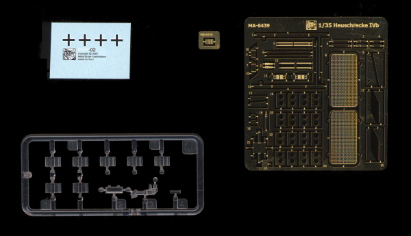
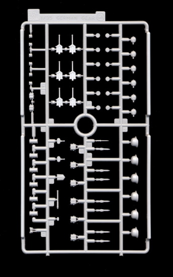
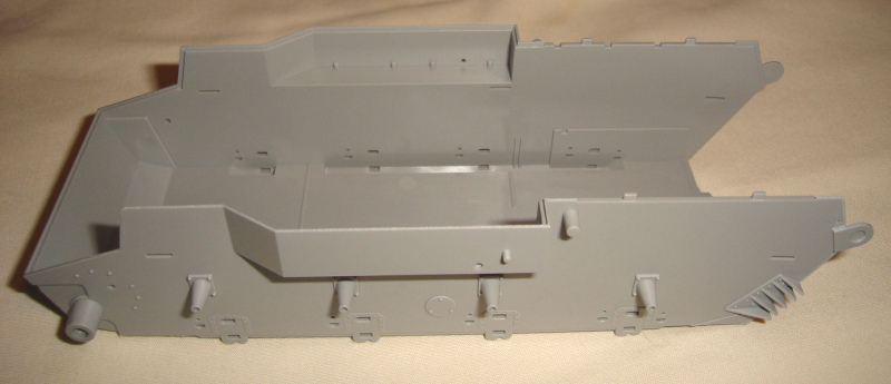
Sprue F comes from a Stug IIIG kit and has the gun breech. The several G and K sprues have tools and vehicle equipment. The GA sprue has personnel equipment, which is odd as there are no figures and none of them are called for in the instructions. H holds the other gun breech and the mantle and turret parts and tree "I" holds the clear parts. MA is a large fret of PE parts while MB is a small fret with a single part. The lower hull is a tub with a separate back plate and there are two bags of Magic Track pieces for the left and right tracks. The decals, printed by Cartograph are simple, consisting of just 4 small crosses.
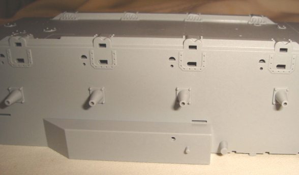
All the parts show Dragon's typical excellence in design and casting. If there are ejection pin marks at all, they are always somewhere that will not be visible once the model is built. The exceptions are up in the bottom of the crane support arms. These marks will be very visible if the crane is in the extended position and are in areas hard to get at. There are no terrible sink holes, although part D9 does seem to have a very slight depression in the middle of the face. While there are seam marks, they are slight and should take little effort to clean up. The exception is on sprue GA where the mess kits seem to have a more pronounced seam.
Review
While going through the instructions, there are many problems/issues to deal with which I will list by Step # as a reference:
Step 1:No, you are not hallucinating. You use different drive sprocket types for left and right. That's the way that the actual Heuschrecke at Aberdeen Proving Grounds (APG) is configured. Were all the prototypes configured this way for some reason? The front part of the idler is A35, not A34. A21(55) is the main bogie assembly. The round part should be A44(45).
Step3:The instructions say to glue the firewall to the floor then glue the combination into the hull but it looks like the firewall should be trapped between two small ribs in the hull. There are notches in the rear of the floor for the front ribs to pass through and hopefully they are large enough and aligned properly. There is no mention of putting shells (D47) into the lockers (D3). The floor is not C13 but C12. C13 is the drive shaft cover which has magically appeared in the diagram already installed. Although it is nifty that you can see the battery, there are no instructions in how to paint it.
Step 4:The parts labeled A18(19) are actually C18(19).
Step 5:There is no mention that the cartridges (D48) can go into the storage locker (D4).
Step 6:This is a bit confusing. Didn't I install the A12s in Step 4? Ah, the last bogie assembly has another behind it. Is it only for this side? It sure looks like there is one on the left side as well.
Step 7:There is an antenna mounted on the rear hull plate. There seems to be a mount there on the APG machine. Was the antenna ever really installed there and they had to remove it (or lower it) when they wanted to use the crane or was it just left over from whatever chassis was used for the prototype? In the inset diagram of Step 7, the part labeled B20 should be clear part I4. I have no idea how or if it is to be painted. From other kits I have, the little squares in part D54 should be painted green.
Step 8:They give you these nice PE visor hinges but why open them if there is no driver's compartment? The vision block (D36) for the visor seems a bit long. Maybe it was meant to be to block the view? There is also no top to it.
Step 9:Part K1 appears already in place in the inset diagram at the bottom without a part number. To assemble the wheels correctly, take a peek at step 21. Only install the wheels here if the turret will be on the vehicle.
Step 11:The front MA15 should be MA9 with the B17(18) really being B7(10). In the inset diagram, MA17 should be MA7.
Step 12:In the inset diagram, the circular D6 is correct, but the D6 at the bottom left should be E1(E3).
Step 13:The gun breech can be vertical or horizontal. It is a nice option, but it would be nice to have some guidance on why one should choose between them.
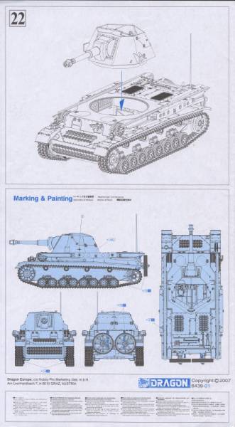
And now for some general remarks on the kit. There is no interior for the driving compartment. This is a serious omission since the turret is not only open-topped but removable. I'm sure the gun breech will block some of the view if the turret is on, but it will be painfully obvious that there is nothing up front if the turret is posed on the crane or on the ground. The turret seems like it should be longer or lower and there's a lot missing for depicting the turret on the crane. For example, there should be a bar that rides along the crane rails as the turret is attached to this bar for mounting/dismounting. I believe it is stored on the port side under the crane rail, but that is just a guess from pictures of the APG vehicle. Attached to the ends of this bar should be wheels to let it ride on the rail as well as pulley wheels and chains for lifting/lowering the turret. You can see this in Tankograd's Militaer Fahrzeug 1/2008.
The side of the box boasts about how the "securing spikes for dismounted turret are slide molded", yet there is no mention in the instructions where they go. When the turret is emplaced, the spikes would normally go into the 3 segment holes in E1, E2, E3, and E4, however the parts representing these holes are not hollow so you can't just insert them into the holes. I have no idea where the spikes are normally stored when the turret is on the vehicle. There are numerous missing paint call-outs (tail lights, headlights, radio, gun breech, ammunition), meaning that assembling this kit will be an exercise in patience and vigilance.
Conclusion
As long as you keep the turret mounted, this is a nice kit of an unusual subject right out of the box. If you want to show the turret being moved, be prepared to add a lot of stuff for the crane. If you want to show the turret dismounted or hanging from the crane, be prepared to add more after market or scratch-built details for the driver's compartment.
References:
Wikipedia
Silicon Valley Scale Modelers Photo Gallery of APG Heuschrecke
www.panzer-modell.de
Tankograd's Militar Fahrzeug 1/2008


Comments