introduction
Initial attempts by the German Army to create a bridge laying tank using the Panzer I and II chassis soon showed that both these chassis were unable to cope with the weight that this entailed. In 1939 the Panzer IV chassis was selected for conversion, and both the Ausf. C and Ausf. D were used. Two very different designs of bridge were trailed, one by Krupp, using a pivoting gantry, and one by Magirus, which used a sliding motion to deploy the bridge. The bridge laying tanks were issued to the 1st, 2nd, 3rd, 5th and 10th Panzer Divisions during 1940, but after the invasion of the Low Countries and France, further production of Bridge Layers was canceled, and the majority of existing ones were converted back to gun tanks.
This new release from Trumpeter depicts the Ausf. D based version, with the Krupp designed bridge. It comes fairly hot on the heels of the 'Munitionsschlepper', with which it shares most parts, and a close look at the sprues shows a number of un-used parts that indicate that we can expect more variants. There are late style crew hatches, and exhausts to name two. Two small triangular notches in the front of the hull may even point toward a future Jagdpanzer IV ?
what's in the box?
The kit comes in a large, sturdy cardboard box, with a top opening lid. The box art by Vincent Wai depicts a Brueckenleger ready to deploy it's bridge over a small river flanked by meadows, shrouded in a morning mist. Inside the box we find:
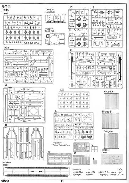
- 9 light gray styrene sprues for the vehicle
- 8 light gray styrene sprues for the individual track links
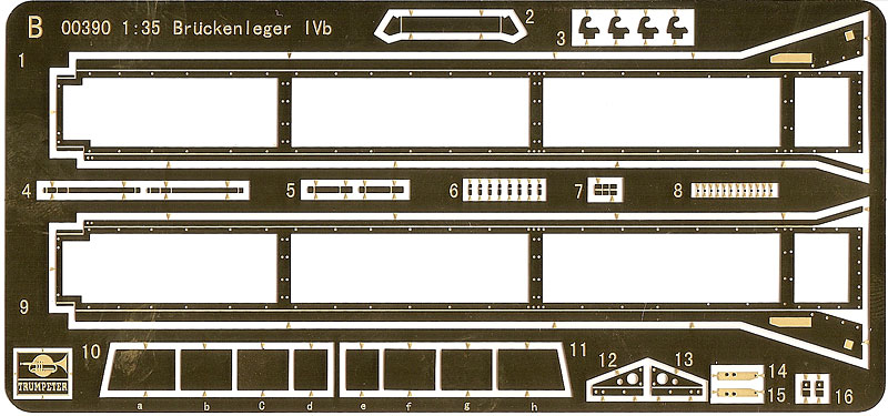
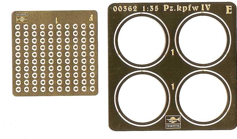
- 5 brass Photo-etch frets
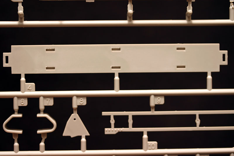
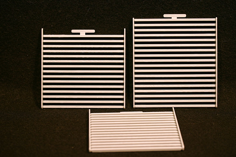
- 3 bridge deck sections in light gray styrene
- 4 small springs
- 6 small metal 'tacks'
- a length of thread
- soft plastic 'rubber band' tracks
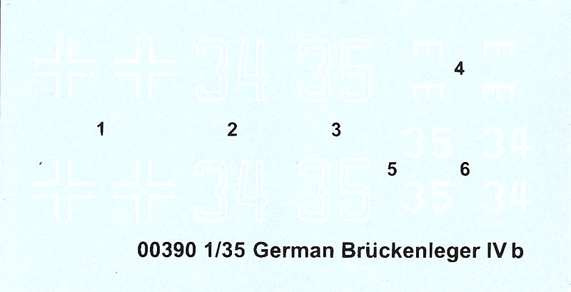
- a decal sheet
- a 28 page instruction booklet
- a sheet in color, with paint and decal instructions
For this review I will use the instruction sequence to go through the kit step by step. Whilst I can not built the kit at this moment, I have dry-fitted many parts to find out if there are any fit issues. A full built feature will follow.
the instructions
The instructions are broken down into 42 steps, over 26 pages. Unlike many other instruction sheets, this one does not contain any information about the vehicle, nor any photographs. The instructions take the shape of 'exploded view' drawings, with which most modelers will be familiar. The drawings are clear enough, using multiple drawings to take the builder through the construction 'step by step' rather than trying to cram everything in just a few busy and confusing drawings. Other manufacturers please take note. All is not perfect though, there are a few translation mistakes in the beginning, and the instructions point out various 'options' along the way, but fail to explain what these options are, and why to chose which. This is particularly confusing in step two more of which in a moment. The instructions for the bridge, the gantry and the support rails are not very detailed, and careful dry fitting will be the order of the day.
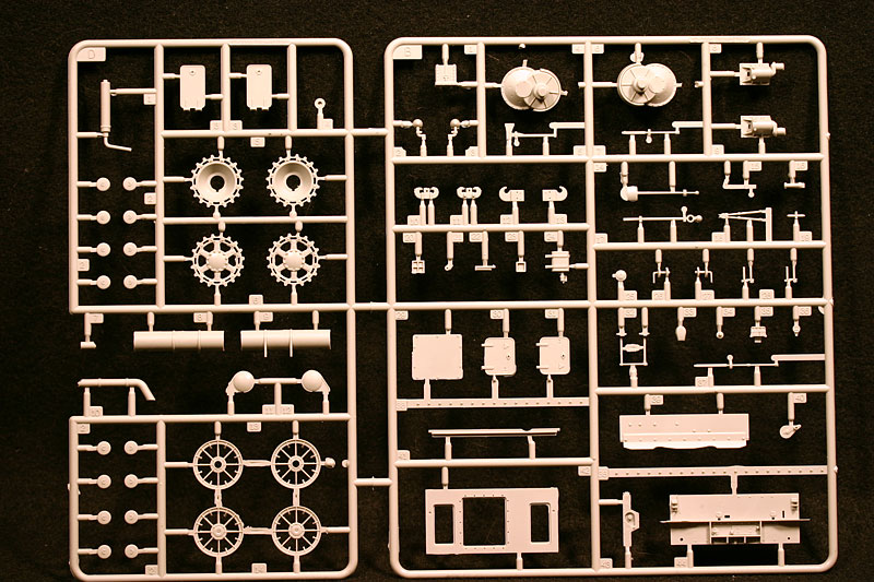
lower hull, suspension and wheels
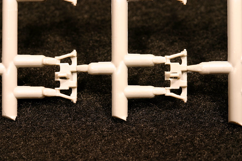
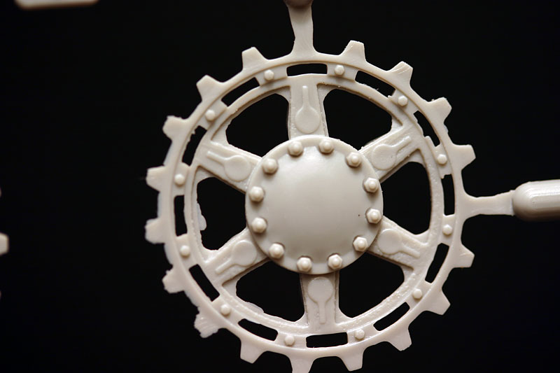
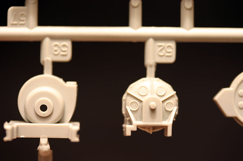
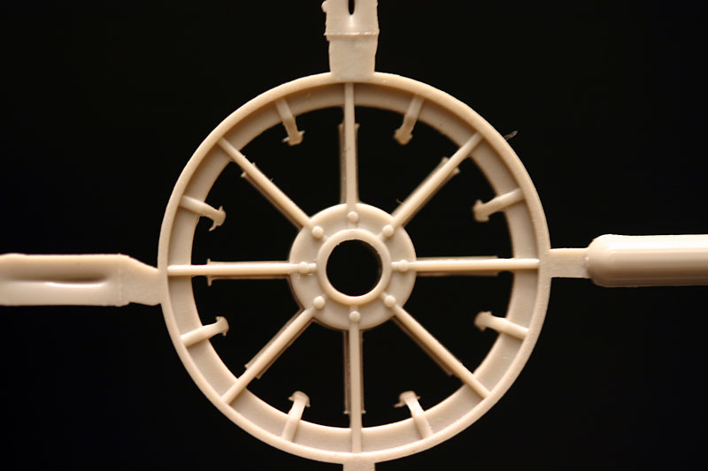
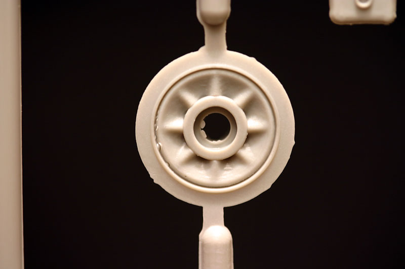
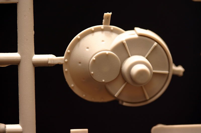
The sprues suffer from a fair amount of flash generally, and particularly the drive sprockets will need careful cleaning up with a sharp Exacto knife. The drive sprocket are good otherwise, with correct, if slightly soft, bolt detail. The teeth line up correctly, and fit well with both the one piece rubber tracks, and the styrene individual links. The idler wheels are o.k., and use two photo-etch rims for extra detail. The return rollers are of a curious design, not the usual early design that was used on all Pzr. IV's from Ausf. A till Ausf. G.
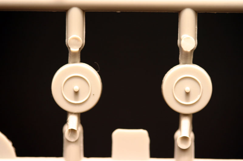
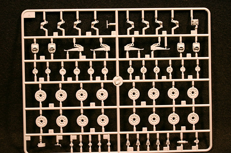
The road wheels are quite basic, with plain tires. The fit of the two wheels together is quite rough, but (liberal) use of liquid glue makes for an acceptable fit. The shoulders (edges) of the tires are quite sharp, but a quick swipe with a sanding stick softens them easy enough. The rim edge where it meets the tire is very faint, and should have been a bit more pronounced. The face of two wheels (of 32, one on each of the two sprues) have not been molded completely, and will have to be used on the inside.
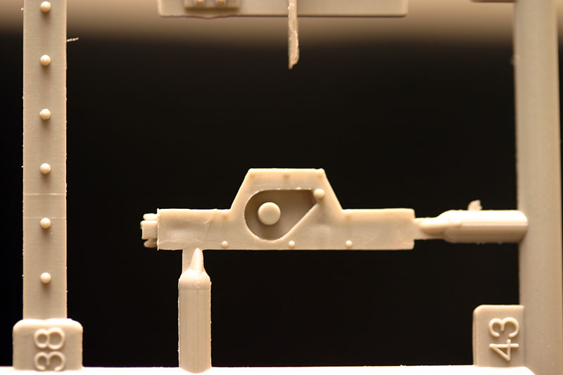
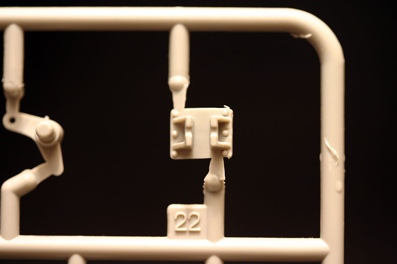
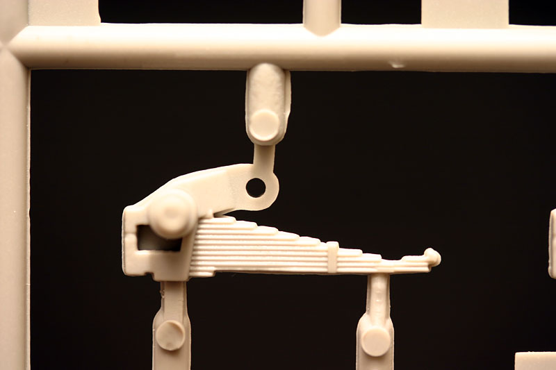
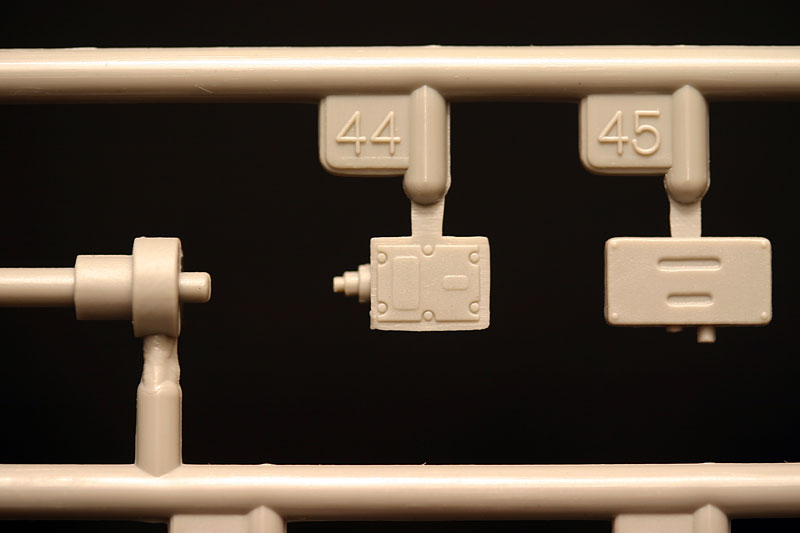
The suspension bogeys are made up from multiple parts, and can be made to move, to enable the model to be posed on an undulating base. The leaf springs lack a bit of detail and finesse, but as they can hardly be seen on the finished model, this is not a big problem. The bogey mounts are fairly well detailed, with the correct number of bolts in the right positions and with basic but correctly detailed cover plates. The rubber bogey stops are also correct for this version (Ausf. D). The bogeys built up without any problems, and the fit of the wheels on the stubby axles is positive but not tight, and the wheels will need to be glued in place.
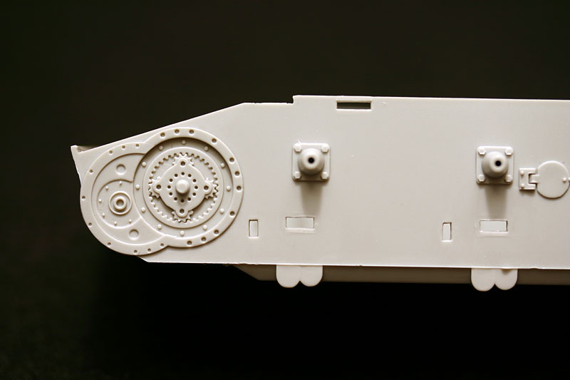
The final drive is detailed on the hull side, but the inside of the final drive housing is not. The final drive housing needs 15 separate bolt heads which you have to shave of the sprue, not an easy of job.
Edit - The Ausf. D used 6 bolts, rather than the 10 as indicated in the instructions. 10 bolts where introduced with the Ausf. E. None of the photos that I have seen show the armoured cover in sufficient detail to show the number of bolts, so it would be safe to go with the 6 bolts of the Ausf D. 36 of these bolt heads are provided, so there is not much room for mistakes.
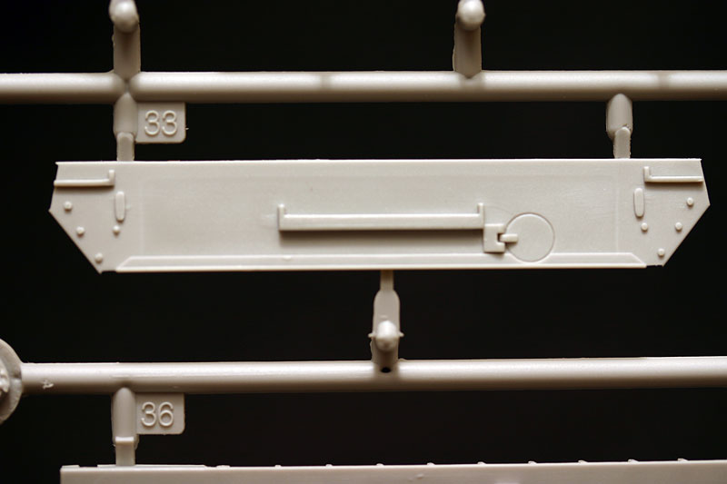
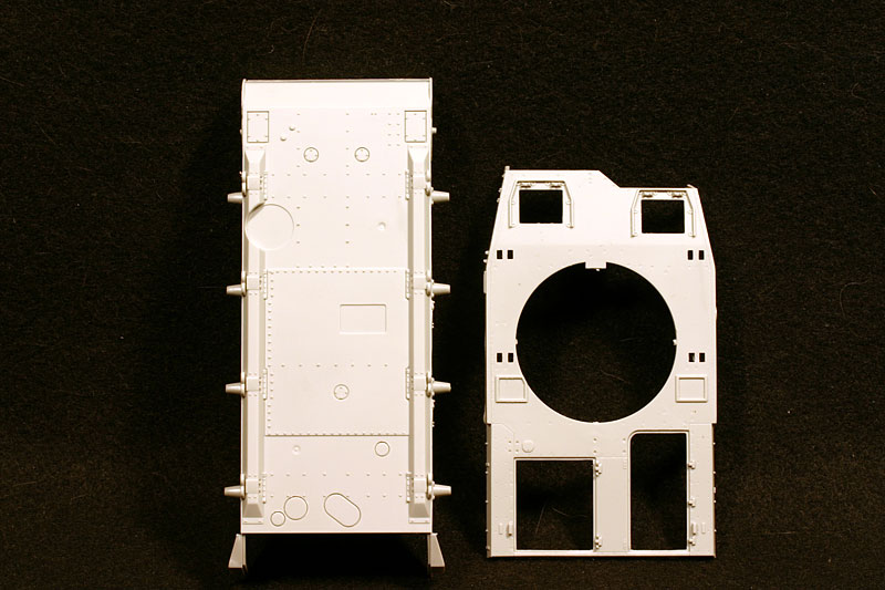
The one-piece hull tub consists of the floor and left and right hull wall. Detail is good, with the various brackets, flanges and bolts all in the right place. The only error is that the bottom of the fuel filler cap hinge should be level with the bottom of the return roller mounting plate. It is slightly lower. The front and rear plates are separate items, again pointing in the direction of future releases of different variants. The fit of these parts is good, but because they lack locating points care needs to be taken during clean-up and whilst gluing them into place. Dry-fitting is essential here to achieve a satisfactory result. The hull tub in my kit is straight, unlike the superstructure, more of which later. The rear plate is straight forward, with the usual details like the exhaust, the cooling water drain, and adjustable idler mounts to be added. The latter are correct in shape and mounting bolts, but lack detail definition.
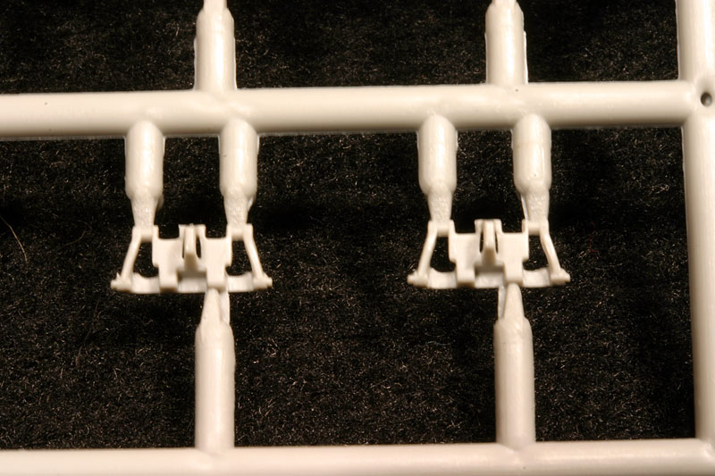
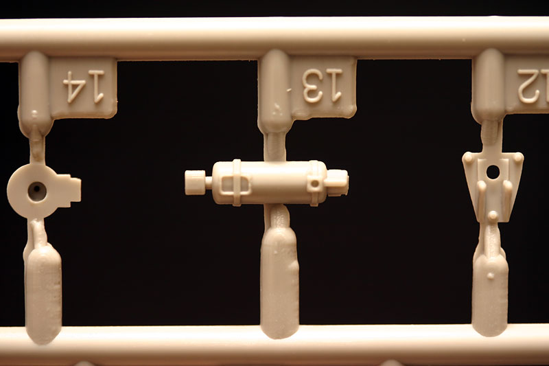
The exhaust (two different ones are provided, one for the 'Munitionsschlepper') will benefit from some texturing, and also has the two bands for the smoke candle rack molded in the middle. These are part of the early smoke candle rack that was mounted to the exhaust. The later rack was mounted directly to the hull rear plate. These bands need to be removed, as no smoke candle rack is used on this vehicle. The rear plate has a number of mounting holes prepared on the inside, (again for future versions) and one of those needs to be opened up to be able to mount the exhaust later on. The instructions point out the correct hole. The auxiliary exhaust was of course not used, as the lack of a turret traverse motor meant that no auxiliary engine was mounted.
The first real confusion is where the instructions indicate that you have two options for the front tow hitch points (step 2). You have the option of either two large brackets (without tow eyes), which seem to be some sort of 'run off ramp' to stop the bridge from damaging the hull front/mudguards during deployment. The other option are two very heavy duty brackets, with tow eyes, which do not offer the same protection to the hull. No indication as to which one should be used why is given in the instructions, so lacking definitive (photographic) reference the choice is up to the builder.
EDIT - After looking over all the photos that I could find, I have to conclude that the 'ramp' style brackets are the ones to choose. I have not seen any photos with the large tow shackles.
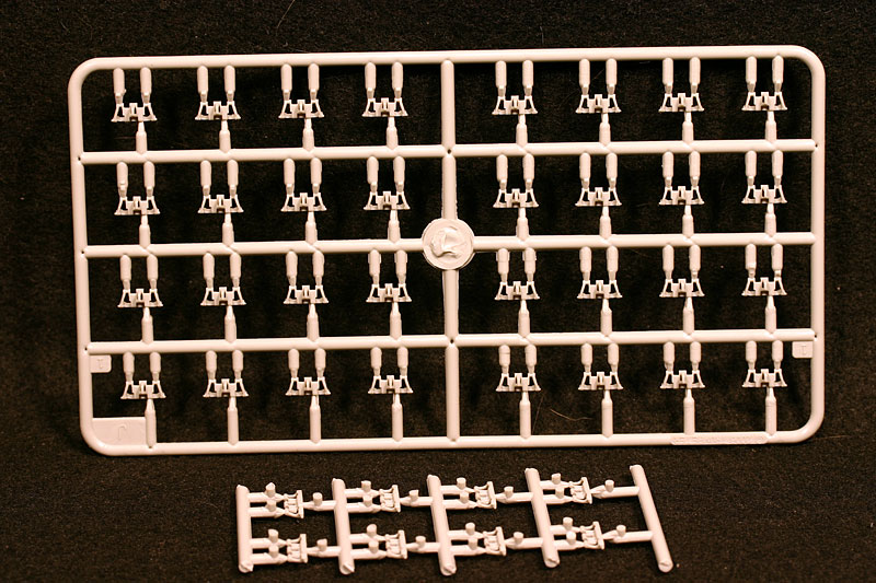
tracks
Two types of tracks are included in the kit, 'classic' one-piece rubber band tracks, and styrene individual links. Both are 36 cm tracks and have the correct open guide horns, a feature usually overlooked on Pzr. IV tracks, even expensive aftermarket ones. The rubber band tracks suffer from the fact that Trumpeter have managed to make them small enough to be in scale (unlike most other rubber band tracks), which unfortunately makes them prone to loosing shape a bit. They also, and this is more of a problem, suffer badly from flash, which is difficult to clean up. The individual links are very nice, with no flash and little clean up needed if you remove them using a flush cutting sprue-cutter. The shape, size and detail of the links is correct for the early 36 cm tracks, with only the casting marks missing. Even the ends of the track pins are present. The links fit each other perfectly, and all that is needed to construct them is a dab of slow setting liquid glue. These are some of the best (plastic) individual links for Pzr IV tracks that I have seen, and I hope that Trumpeter will release them separately.
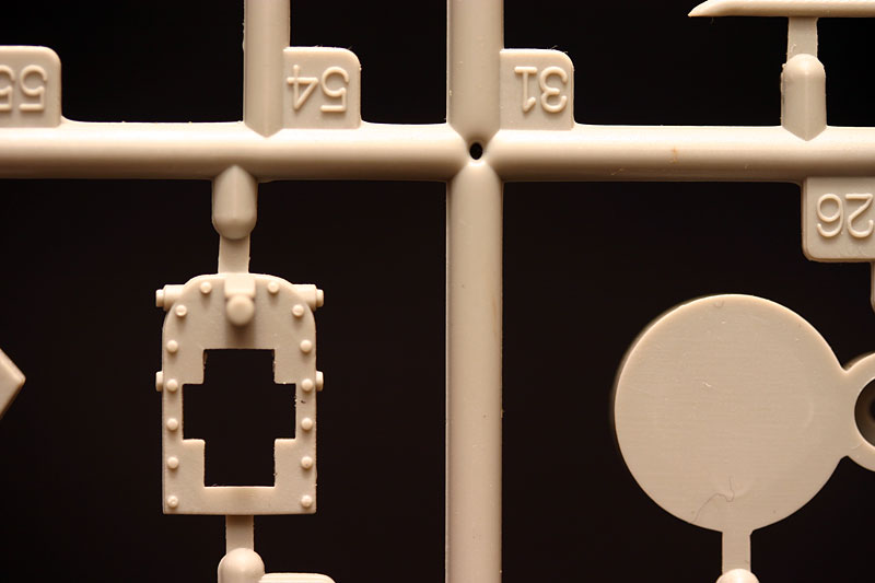
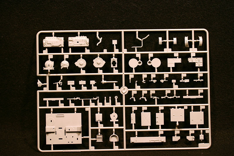
interior
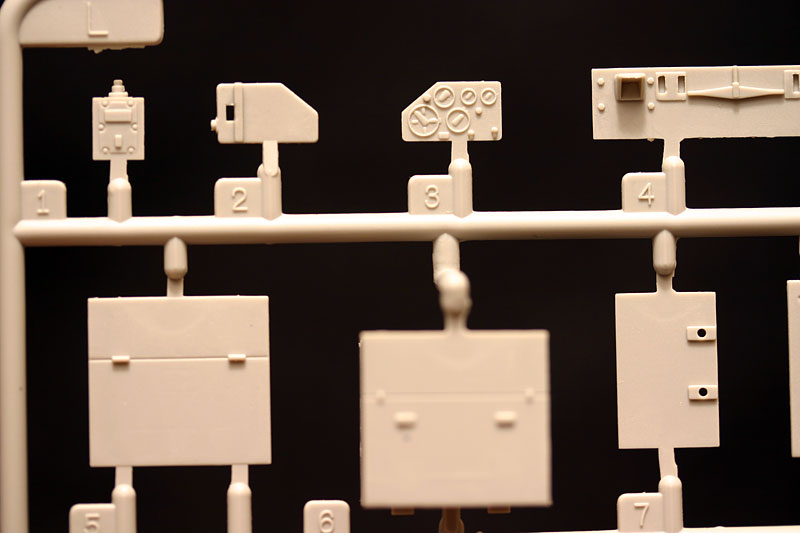
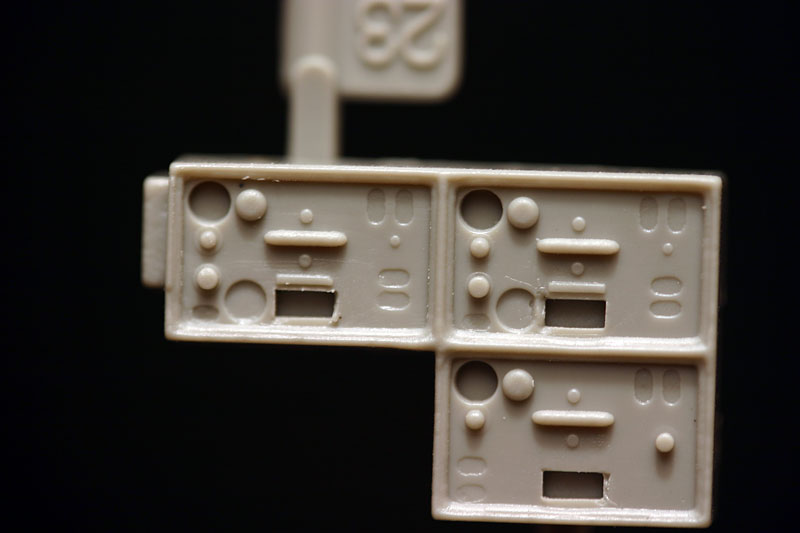
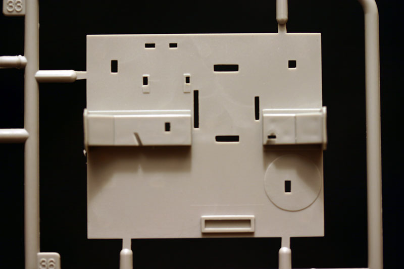
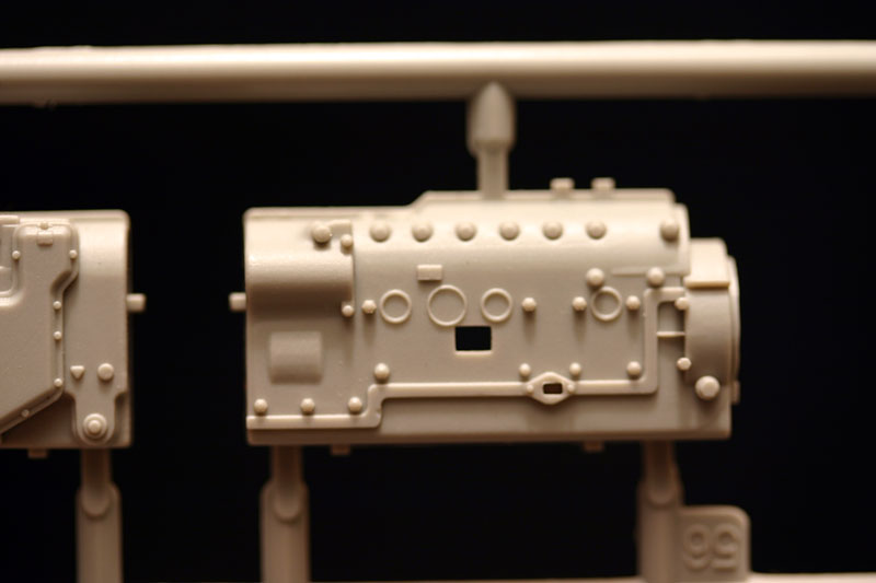
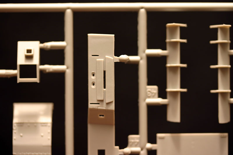
The inclusion of a complete driver's and radio-operator's interior, which will be impossible to view once the bridge is mounted on top, is as laudable as it is baffling. More so since it is a highly detailed interior, with only two inaccuracies. As far as my references show, the radios are mounted differently than depicted in the kit. It is however possible that this configuration was used on the Bruckenleger, but as the front of the hull has not been changed this seems unlikely. The other slight disappointment is the driver's instrument panel. The layout of the dials and switches is spot on, but the dials have some raised detail, depicting the dial needles, which is massively over-scale and poorly detailed. Considering that you won't be able to see this detail is small consideration.
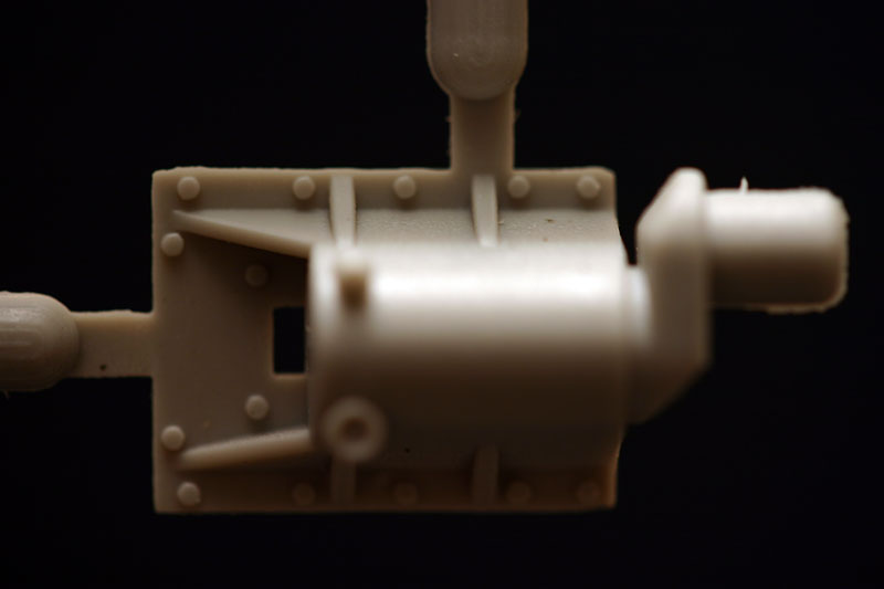
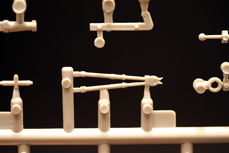
These two errors notwithstanding, the interior is very well done, and would be a great addition to another model, where it will be more visible. The gearbox is very nicely detailed, the drivers side fuse panel is there, even the cooling air ducting is correctly depicted. The drive-shaft driven centrifugal fan for the brake cooling air has a universal joint connected, which again gives an indication that more is to come in the future. If this 'front office' is anything to go by, I can't wait to see the turret/fighting compartment.
upper hull assembly
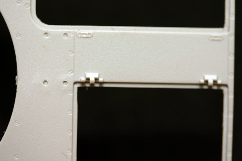
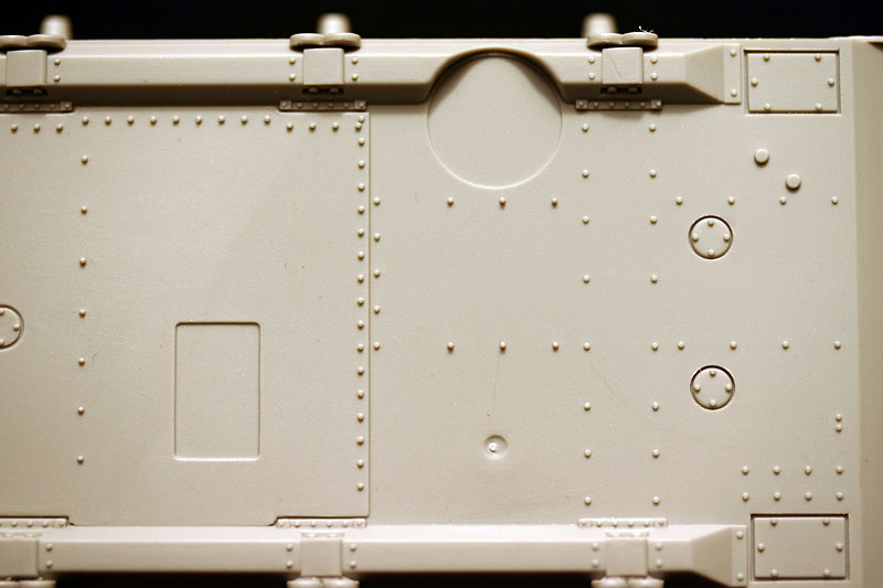
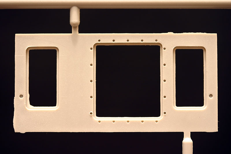
Dry fitting most of the major upper hull parts has not indicated that there should be any major fit problems. Most of the mating surfaces will need careful clean-up though, as these parts do suffer from flash, and some awkward knock-out marks. Surface detail includes the myriad of sunken screw heads that seem now obligatory on the Pzr IV, and some weld detail. The main upper hull part in my kit is unfortunately warped at the rear, but it looks like this will be easy to fix when it all gets glued together.
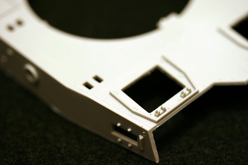
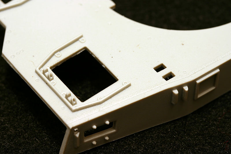
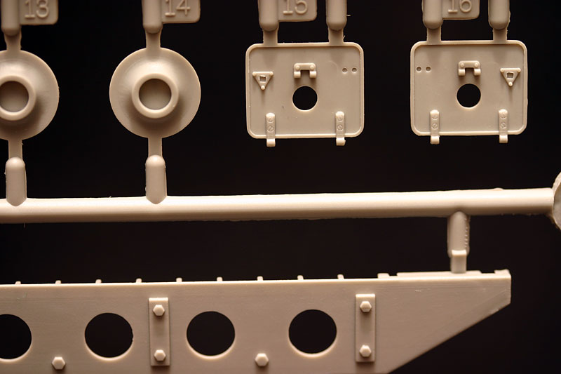
The brake drum access hatches in the front glacis have a smooth raised edge along their edge, this is wrong as it should be a slightly raised weld just inside from the edge. The hinges are a solid molded affair which makes it impossible to open these hatches without scratch building them, which, given the interior detail that is included, seems a curious short-cut. The lock plate is attached to the hatch with three screws, the orientation of which looks to be 180 degrees out. All the photos that I have show one screw facing forward and two screws facing rear, whilst many drawings show the Trumpeter way. No fit problems after cleaning up the mating surfaces. The central transmission hatch has slotted screw heads to secure it, which is wrong. This hatch was secured by square headed bolts, which sit prominently prone of the surface. It is well worth the effort to remove the molded slotted screw heads, and replace with small square pieces, which can easily be sliced of a small piece of square plastic stock.
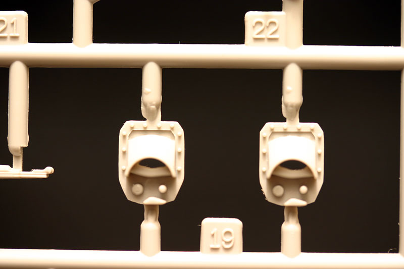
The driver's and radio operator's hatches have separate signal ports, with fine hinge detail, including slotted screw heads. The molded triangular keyhole plate on the driver's hatch is 180 degrees out. The splash guards show equal fine detail. The inside of the hatches is not detailed at all, but has some major knock-out marks at any rate. Fitting them closed is really the only option, making even less of a case to build the interior.
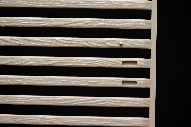
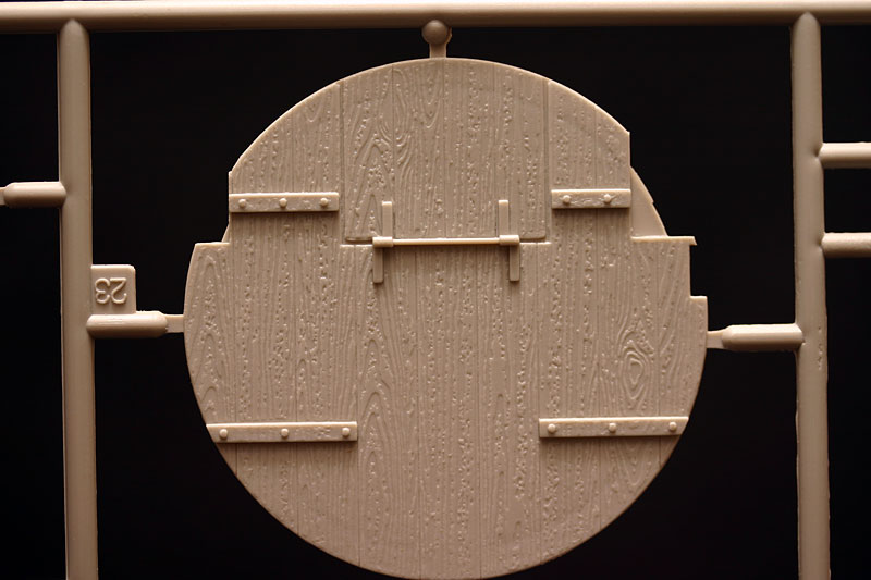
The large wooden cover that closed the turret aperture is replicated very nice, with good looking, raised, woodgrain. Sanding the woodgrain down a touch will probably improve the scale appearance, even though, you guessed it, this will also largely be hidden underneath the bridge.
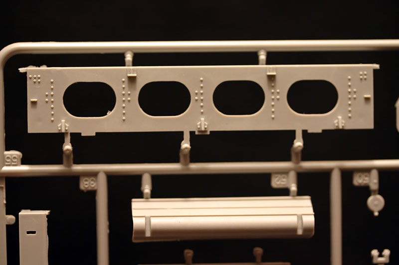
The engine deck on my kit is slightly warped, but that should be fixed when it gets glued to the rest of the hull. Again a large number of flush and sunken screw heads, the bigger of which are slotted. The weld beads along the top edge of the air intakes are missing, instead having another row of (small) sunken screw heads. This is a feature that is missed on all Pzr IV kits that I know of. The weld along the top edge of the superstructure is present, although it is not quite following the mating edge of the hull plates at the left front. The access doors to the engine compartment are a good fit, again after clean-up, and the key holes are molded quite well, not too big, with rectangular holes and two screw heads.
mudguards
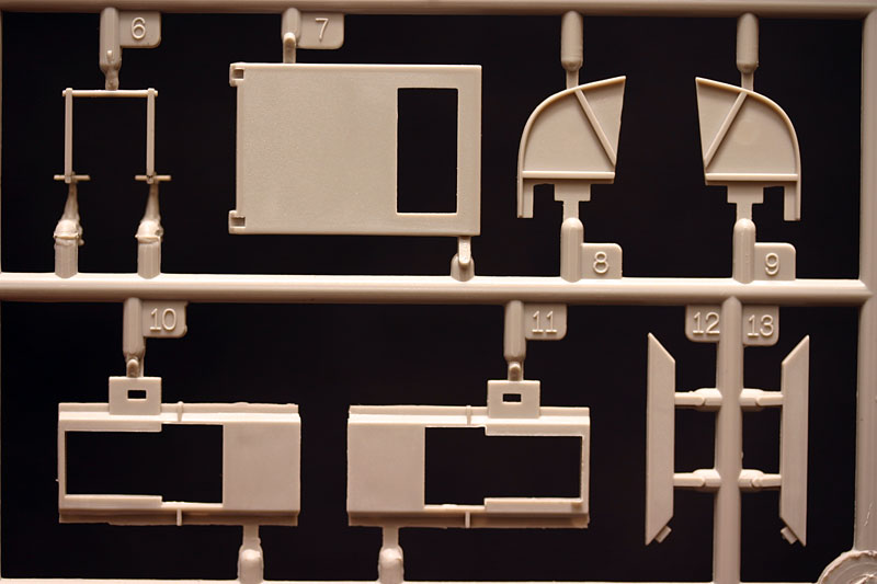
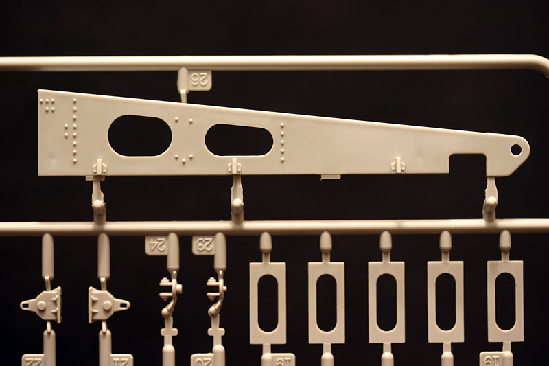
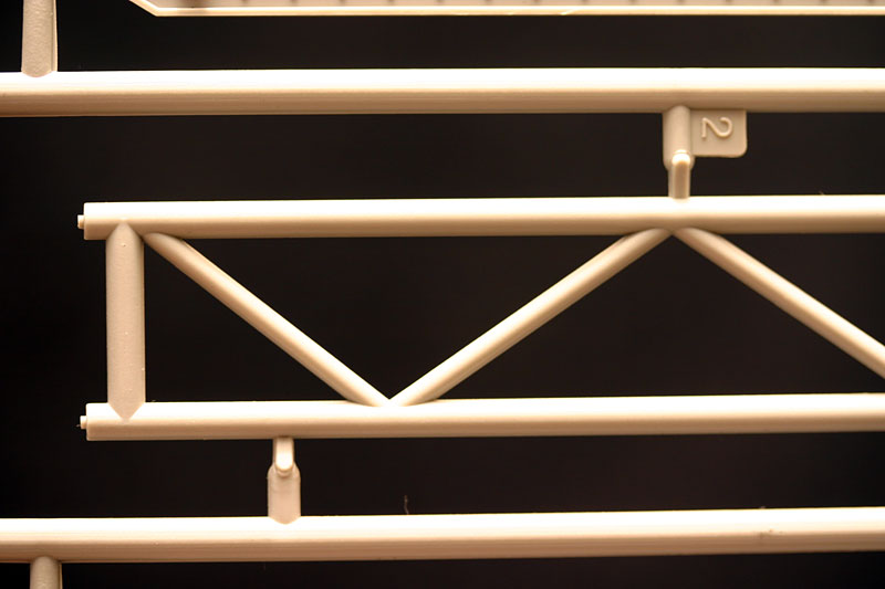
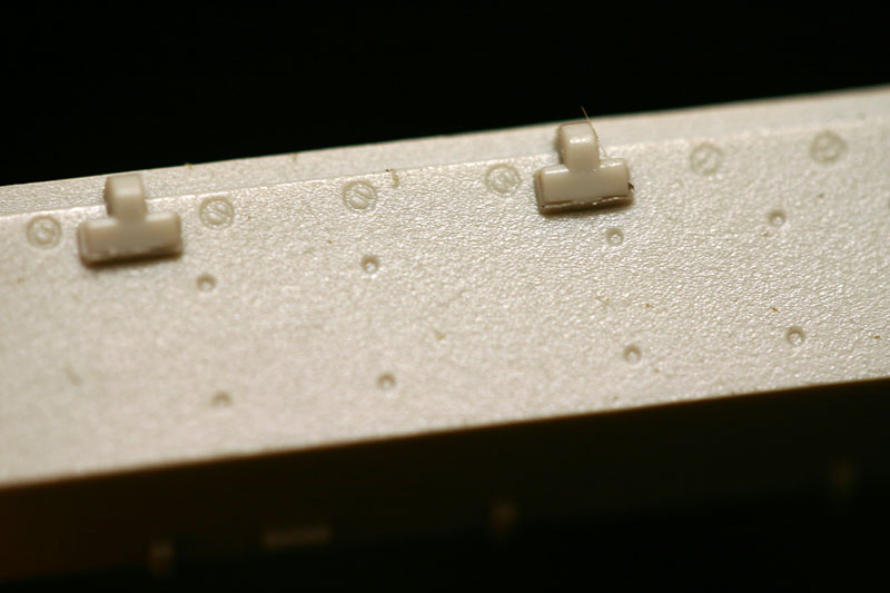
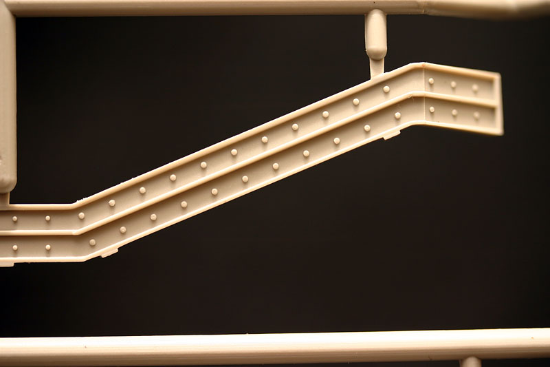
The mudguards are a feature were Trumpeter come up trumps again (sorry for the poor pun.). Two options are included, plastic and Photo-etch. And not just plain Photo-etch mudguards either. The mudguards are built up like the originals, with a separate angle-iron framework, on which the tread plate mudguard panels are attached. The tread plate is unfortunately only detailed on one side though. Photo-etch hex bolt heads are provided (fret F, 100 pieces) if you would wish to add these as well. You will still have to make a number of your own, as the 100 supplied bolts are not enough. The rear hinged mudguard panels have the slotted screw heads already etched in-situ. The front mudguard hinges can be made workable, and combined with the real springs should look superb. The rear mudguards in contrast are not provided with hinges at all, but do have the springs attached. I am not sure if the rear mudguards were attached solid on the real vehicle, as non of my references show this detail clear enough. The hinged air intake covers are separate items, so you could show them opened or closed. They have no other detail, such as the hinges, and retaining clips, so for accurate detail these will have to be scratched.
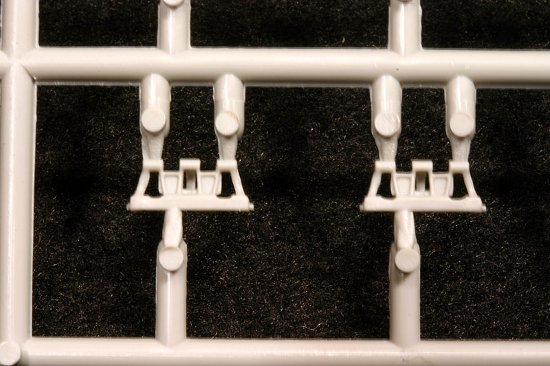
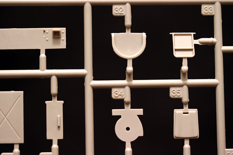
The styrene mudguards are in one piece, with the hinging parts molded solid in place, but you still get to add the real springs for enhanced detail. The thread profile is slightly larger on the styrene parts than on the Photo-etch ones, but the styrene parts have major knock-out marks on the underside. A quick swipe with sandpaper should be sufficient however, as the tracks run close enough to the mudguards to make the underside all but impossible to look at. The styrene mudguards have locating holes for all the tools etc, as well as the hinged air intake covers molded in place. The tools are all molded with their various mounting brackets and clamps, and are basic but adequate. The Notek light is very nice, and has bolt and bracket detail underneath. The mudguard mounted step is best discarded, as the Photo-etch fret contains a replacement (PE-A21 and -A22) including hinges (PE-A11), although this option is not indicated on the instructions. The tow clevis set is very crude, and just about un-usable, the carry handles being the completely wrong shape and size.
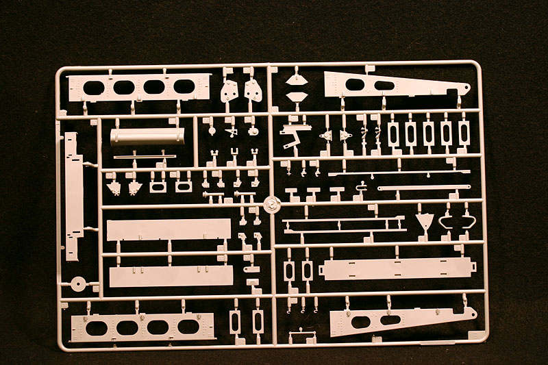
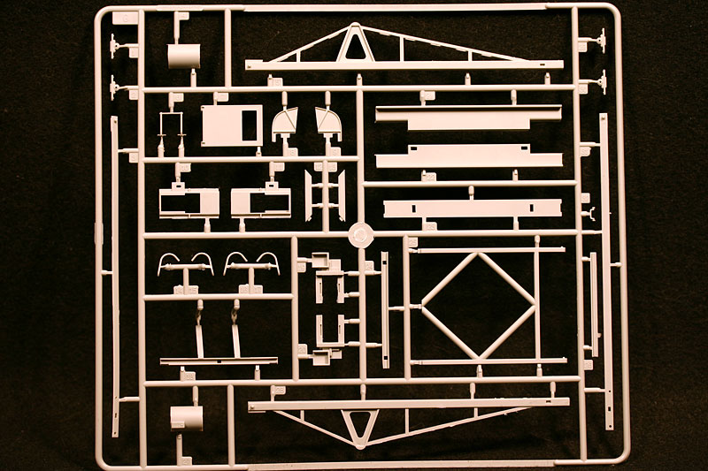
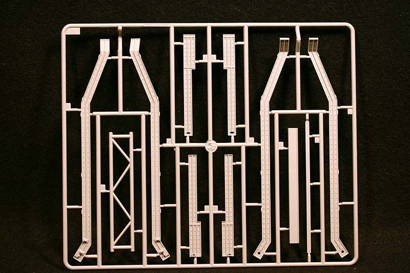
the bridge
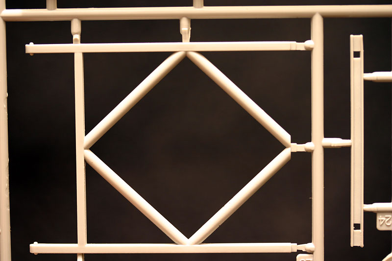
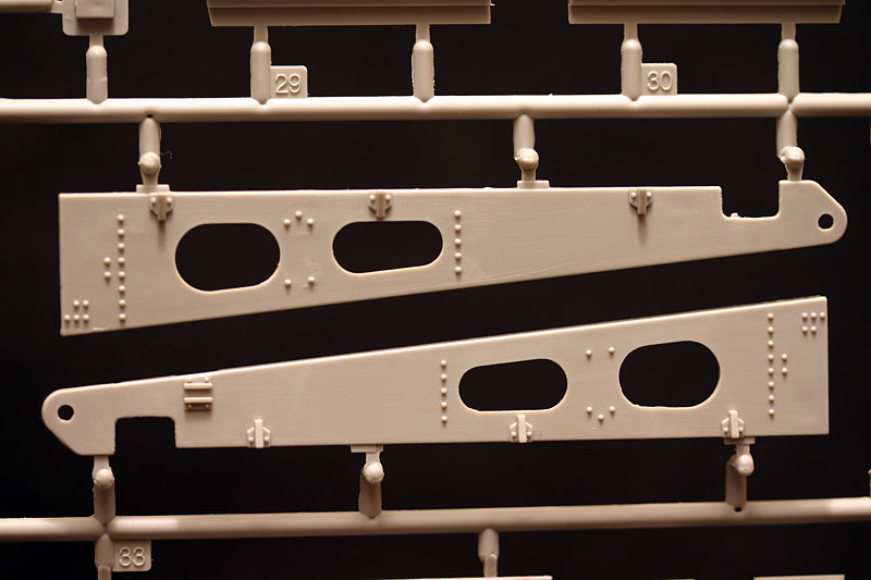
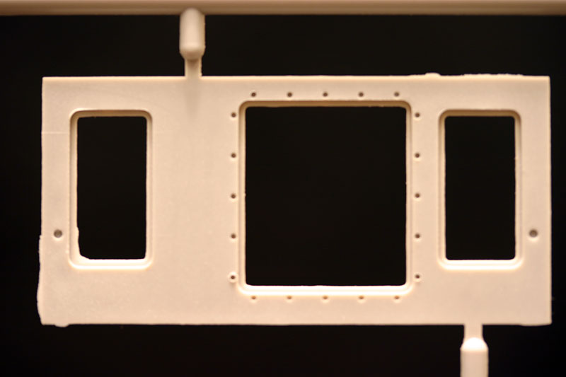
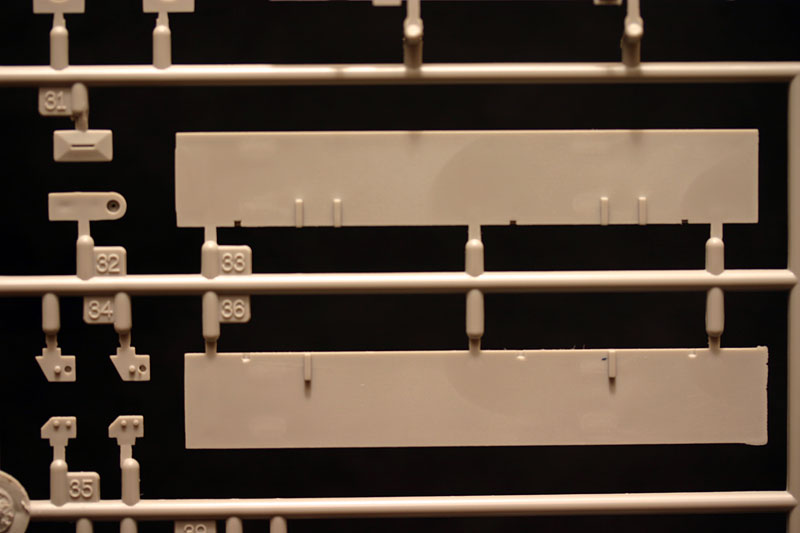
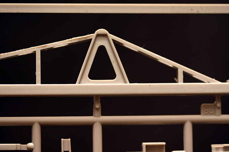
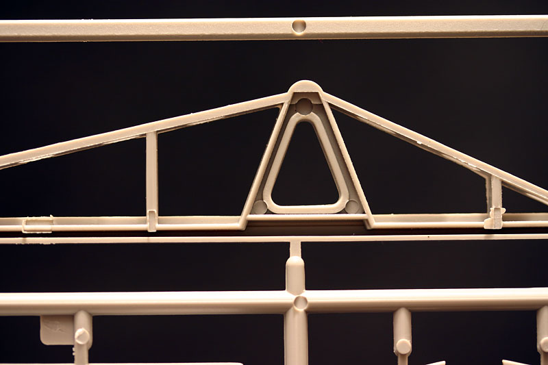
Finally then, the main part of this kit. General fit of the parts is good, but again the mating surfaces of the parts need to be carefully cleaned up. Almost all the larger parts suffer from serious knock-out marks, some of which will be visible on the finished model. The majority of these are sunk, necessitating the use of filler in most cases. The surface detail is nice, with well defined rivets, and careful comparison with the photo's that I could find, shows the general shape, size, and detail such as the various holes etc, to be correct. The wooden decking has been recreated quite convincingly, but as with the wooden turret aperture cover, the woodgrain will improve if it is sanded down a bit. It looks like the bridge can be built 'workable'.
markings
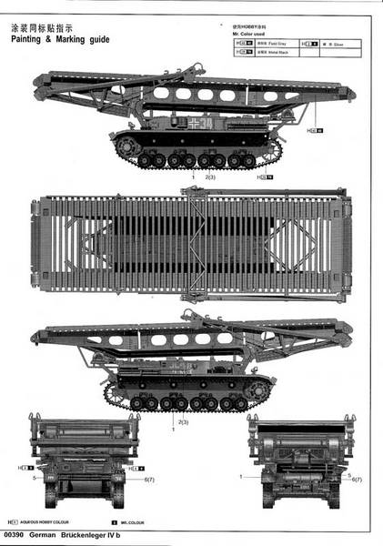
The short career and limited use of the Brueckenlegers limit the possible marking option substantially, and this is reflected in the Decals that Trumpeter have included. Two sets of identification numbers (34 and 35, one of small solid numbers and one of the same numbers in larger outline), four national 'Balkenkreuz' markings, and four Divisional markings for the 3rd Panzer Division. The Decals are in plain white, which is fine for the numbers and 'Balkenkreuz', but the Divisional markings were applied in yellow. The numbers are correct, having been inspired by photos of actual vehicles. I found a photo of vehicle No. 35, with the 3rd Pz. Div. sign painted on the right rear mudguard, posted in a thread on the Axis History Forum.
conclusions
An injection molded model of the Pz.Kpfw. IV "Brueckenleger" has been on many modelers' wish lists for many years. When Dragon announced one (how long ago now?) anticipation was high, as this model is both an impressive 'stand alone' model, as well as a superb centerpiece for a diorama. Finally then, Trumpeter has obliged us, and given us a model in styrene, with a sizable inclusion of Photo-etch detail to boot.
One piece rubber tracks with open guide horns and miniature 'real' springs for the mudguards, are just two of the welcome additions that will benefit not only this kit, but also future models of the Pz.Kpfw. IV. The kit is full of indications that Trumpeter is planning on expanding the range, the late style crew hatches for example. The interior is very good, and it is a pity that this kit will make it virtually impossible to view, I'm sure that it will find it's way into many other Pzr IV models. The Photo-etch mudguards are a real treat, and with the level of detail that is normally reserved for expensive after-market sets.
The kit is not without it's faults, suffering from to much flash and knock-out marks. The suspension and wheels are disappointing, and I hope that Trumpeter will re-tool these parts when they release future versions. Other errors are not outside the scope of the experienced modeler to remedy, such as the wrong bolt heads on the transmission inspection hatch and the wrongly orientated lock plates.
A very welcome new addition to the growing family of Pz.Kpfw. IV models, and one which I look very much forward to start. Highly recommended.
references
- "Pz.Kpfw. IV Ausf. D Up-Gunned" (Modelart)
- "Auchtung Panzer No.I Panzerkampfwagen IV"
- "Panzer IV, Sd.Kfz. 161" (Kagero)
- "Panzer IV, the Wehrmacht's armored fist" (AF Editions)
- "Encyclopedia of German Tanks of World War Two"
Various on-line resources
My thanks to
Trumpeter for this review sample.


Comments