INTRODUCTION
Rick Taylor wrote an
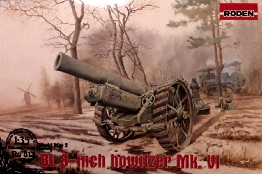
in-box review of the Roden 813 1:35th scale BL 8-Inch Howitzer Mk. VI in January 2019. After reading that review Russ Bucy started building the howitzer and the Roden Holt 75 artillery tractor. As we are in the same IPMS chapter and were both working on the same kit, we decided to write a joint build review with one in firing mode and one in traveling mode. Russ decided to depict his BL 8-Inch in traveling mode with limber and platform being towed by the Roden Holt 75 in the 58th Coastal Artillery Regiment, American Expeditionary Forces in France in 1918. Rick decided to build his in firing mode deployed on the platform in the 44th Coastal Artillery Regiment, American Expeditionary Forces also in France in 1918. Russ wrote a separate build review of the Roden Holt 75 artillery tractor. For a brief history of the weapon system, see Ricks
review on Armorama.
THE KIT
This is the first offering of this subject in 1/35 scale. Roden, of the Ukraine, released a 1:72 scale version in 2018. Resicast offers a 1:35th scale BL 8-Inch Mark II in resin which was a completely different interim howitzer based upon old naval gun barrels. The kit appears to be dimensionally accurate. It does appear that Roden used a post-WW1 museum example for the master. So, there are a couple of changes and corrections required to bring it back to WW1: wheel treads and removing the recoil oil reservoir. These are covered in the build description. The kit molding is a mixed bag. Some of the parts are finely detailed and crisply molded. Other parts are vague and poor fitting. With a bit of work, it can be built into an impressive model. If you wish to enhance the detail of the model, you will need a copy of the US Army manual which is available on the web as a PDF. For box contents, see Ricks
in-box review on Armorama.
WHEELS
On most towed artillery, the eye is immediately drawn to the barrel - not so on this piece. The eye is instead drawn to the head-high steel tractor wheels. However, the kit wheels provide a challenge. There is a deep recessed ejector pin mark on the outside of each of the spokes that must be filled and sanded. Rick used Mr. Surfacer 500 while Russ used Tamiya Gray thinned with Tamiya thin cement. Follow the instructions carefully as it is easy to assemble the wheels and hubs backwards. Getting the spokes and hubs joined is a bit fiddly. The fit between the spokes and hubs is loose leaving big visible gaps in an area that is very challenging to sand. Flow Mr. Surfacer 500 or thinned Tamiya Gray putty into the gaps with a 000 brush. After several careful applications of thin putty, the gaps were filled without the need for sanding.
The US manuals describe the wheel treads as steel not rubber and show the treads opposed. This is backed up by period photos. The kit tracks are not opposed and represent the post war rubber treads. In addition, they are wavy. If you want a more accurate representation of the howitzer as it appeared during the Great War, you have two options for correcting the tread issue. It is not difficult to scratch build new treads with some styrene strip and rivets; but it is time consuming. You can save that time by using Model Cellars newly announced
resin wheel detail set. The initial samples did not reflect the opposed or mirrored tread pattern. Model Cellar is releasing a corrected set.
Scratch building the wheel treads is made easier by the fact that Rodens instructions include an almost full-size diagram of the vinyl treads that can be used as a pattern. The rim is .020 styrene wrapped and glued around the wheels. Evergreen strips .020 x .100 where chopped into roughly 1.5cm long pieces for the steel treads. Photocopy the tread drawing from the instructions at 98% reduction onto a piece of clear acetate overhead projector film for your pattern. This is then cut in half lengthwise and wrapped around one edge of the wheel. Glue one edge of the tread strips to the wheel using the pattern to get the correct spacing and angle. Once the tread strips are all in place, carefully pull out the acetate pattern and glue down that edge of treads. Set that wheel aside to dry. Reverse the acetate pattern and wrap it around the other wheel to place the opposed treads. Once the glue is dry, use a sharp sprue cutter to nip off the overhanging treads flush with the edge of the wheel. A couple of passes on a sheet of sandpaper and you have a nice wheel.
Photos and the US manuals show a lot of very prominent rivets on the wheel tread and the inside surface of the wheel rim. Photos show at least four different rivet patterns in WW1. By far, the most common are two rivets between every other tread or four rivets through each tread. Both of us decided to go with the two-rivet pattern. Russ used Archer decal rivets to add these. Rick used Meng rivets. There should also be lines of rivets on the underside of the wheel rim, both inside and outside edges, and between the spokes. Again, Russ used the Archer rivets and Rick used Meng rivets.
SPADE
It is decision time when you get to the spade. If you are depicting the howitzer with the platform, you need to use the part 23B thrust plate. If depicted without the platform, use the part 11A spade. The kit includes two grab handles, part 4D. These have a prominent mold parting line. They are easily replaced with bent wire stock. The instructions are missing two copies of part 20D. These should be placed against the brackets on the rear top of the spade.
BARREL AND RECOIL SYSTEM
As with most artillery models, the barrel seams require careful filling and sanding. The recoil oil reservoir, part 30B, was added to the howitzer post-war. If depicting a Great War howitzer, this should be left off and its mounting bracket carefully removed from the barrel. The fit of the barrel liner leaves a big gap at the breach ring which must be filled and sanded. The breach and breach block lacks the stepped interrupted thread locking mechanism and so should be depicted with the breach closed. Excellent photos are available that aid the modeler in adding more detail to the breach block and breach. The barrel/recoil attaching lug molding was vague. Carve and sand off the vague stuff and replace with a styrene disk and a LARGE nut.
The bottom of the recoil system cradle, part 4B, does not fit flush with the sides, parts 1B and 2B. Use some .005 sheet styrene to bring the bottom flush and fill the seams with thin putty. The recoil system is not represented in the kit and the big empty recoil cradle is visible under the barrel. Russ opted to represent the recoil system with styrene rod while Rick used sheet styrene to cover the empty space. There are large sinks around both trunnions on parts 1B and 2B that must be filled. Use a sandable primer such as Alclad to check and touch up the all the barrel seams.
UPPER CARRIAGE
The manual brake rod, part 6D, was replaced with styrene rod to avoid the mold parting line. The upper carriage cheeks are molded in two halves, parts 10A and 6A for the right cheek and 5A and 9A for the left, leave a large seam when joined. The top edges of the cheeks each have a line of rivets with a mold parting line down the middle. Russ opted to carefully scrape the mold parting lines, fill the big seam with thinned putty and then use a very small file and folded sand paper to smooth the seam. Rick opted to slice off the molded in rivet detail on the top edges of the cheeks, fill the seam, and replace the rivets. The Archer rivets did not match to the other molded in rivets; so, new ones were punched from .010 styrene with a 0.5mm punch. Using drawings in the US manual as a guide, Rick added several missing rivet lines on the outside of the stock cheeks. The fit of parts 22B, 12B, and 21B is poor and requires filing, dry fitting, and putty after gluing. Part 7B had a large sink on the back side which requires filling. Leave off the elevation handwheel, 2D, until ready to paint. The sight and sight mount, part 10B is lacking detail. Using diagrams in the US manual, Rick detailed this with disks punched from styrene, styrene rods, tubing, and PE retaining chain. Parts 25B and 9B can be glued in place once the elevation of the barrel is determined and the barrel assembly glued in place. Alternately, it would not be difficult to make this articulate.
LOWER CARRIAGE
Part 17B and 18B include a molded in shovel and molded in handspikes. Russ opted to leave these as is and handle with careful painting. Rick opted to grind them off and replace. In doing so, some rivet detail and mounting plates were damaged and had to be replaced with strip styrene and punched rivets. The handspikes are 1.2mm rod and the shovel is from the spare parts box. Mounting hardware was cut from scrap PE frets and bent to shape. The fit of the break / axle subassemblies is poor.
Carefully file and dry fit to ensure proper wheel alignment. After gluing, putty up the large seams. Holes were drilled and reamed in the towing pintle using photos for reference. Two parts 20D, handspike brackets are missing from the instructions in step 8 and should be added to the top rear of the trails in the molded brackets. Part 12B in instruction step 10 is mislabeled. It should be part 31B, the traversing mechanism. This is best glued to the trail in step 8 as the fit is poor and requires filling, filing and sanding. Photos and the manual showed missing lines of rivets; Rick added these with punched styrene. Rick also used photos to add PE footman loops. Leather straps came from thin lead sheet with PE buckles.
Care is required in step 10. The wheel brakes fit nicely inside the wheel rims. These should be glued with a slow drying thicker glue and the wheels dry fitted before the glue sets. Parts 15B and 16B should be glued in only after the upper carriage assembly is mated to the lower carriage. These have big gaps that must be puttied. If depicted in traveling mode, the travel lock, part 3B, should be positioned across the trails and retain the lower recoil assembly. If the weapon is depicted in firing mode, the travel lock should be positioned along the top of the right trail flask. Leave off the traversing handwheel, part 2D, until just before painting. Leave the wheels off to be painted separately.
LIMBER
Russ built the limber according to the instructions with just a couple of modifications. The howitzer manual lists the BII (Basic Issue Items) which clearly indicate where the accessories for the gun were stowed. One of which was a "picket line" to be stowed "on" (as opposed to "in") the Limber along with a 12'x12' canvas tarp and two wool blankets. The tarp and blankets were what the poor souls who rode on the all metal limber would sit on. Since there isnt a crew yet for the gun, Russ decided to save those for a later addition. The four "U" shaped projections on the front of the limber represent the four "clips" for the picket line storage, so Russ hollowed them out to receive a length of appropriately sized thread to represent the "picket line".
Russ drilled out a small hole in the Limber's towing pintle towards the top for a "locking pin" to slip through. For a lack of clear information, Russ made this pin from a length of brass rod, attached to a miniature chain which was in turn mounted on a brass eyebolt drilled into the towing pintle mount.
FIRING PLATFORM
The wood and steel firing platform is unique and a nice addition to the kit. It helped stabilize the weapon to improve the rate of fire by absorbing recoil and limiting displacement during firing. It also prevented the howitzer from burying itself in the mud that dominated the Western Front. The platform can be built in firing mode with the howitzer sitting atop it; or, in travel mode on its wheels and towed behind the howitzer. Rick opted for the firing position and Russ for the traveling mode.
The side braces, 17D, are glued to the wheel platform, 3E, with the closed end of 17D up and aligned to the outside edge of 3E. If so desired scribe in seam between the steel plate surface and the wooden beams below.
In firing mode, step 13b, the platform looked awfully plain. Examining line drawings in the manual revealed that the kit was missing steel reinforcing plates on the side beams, a couple of braces, and the rope grommets that were used by the crew in emplacing and displacing these big, heavy beams. The reinforcing plates and brackets where added with styrene strip and Meng bolt heads. The rope grommets were fabricated with copper wire, styrene strip and Meng nuts. These added details made the platform much more visually interesting.
In travelling mode, the platform was built in accordance with the directions. However, were Russ to do it over again, hed replace all the wooden parts with real Basswood strip. If you don't, the underside of the platform is all hollow. Russ did an excellent job of simulating wood grain with his painting method.
PAINTING AND WEATHERING IN TRAVELLING MODE
Russ followed the same procedure in painting the howitzer as he did for the Holt Tractor, with a base coat of Tamiya Khaki Green which was followed by a coat of Tamiya Khaki on the upper surfaces. This combination produces a nice base of olive-yellow-green-khaki common to American vehicles during WW1. Russ used Tamiya Red Brown for the US camouflage scheme. Following the base coat, Russ used the "Silly Putty" method for the demarcation of the brown areas. After airbrushing these areas, Russ removed the Silly Putty and proceeded to brush paint the black outlines of the brown, being careful to try and keep the black lines uniform in width. Russ then weathered the gun, limber and firing platform with a dot filter using his standard Turpenoid Light based dot filter oil wash, along with a Windsor & Newton Burnt Umber and Turpenoid Light oil-based pin wash.
Russ painted the platform in the base colors the same as the rest of the gun and the Holt tractor. His first inclination was to leave it in the standard Tamiya "Khaki Green & Khaki" paint but upon studying the howitzer manual's, decided these platforms were probably left in natural wood. Therefore, the "wood" parts where given a dark brown Windsor & Newton oil wash, and when dry an oil paint "fan brush" to add some wood grain. This was followed up with dark and light brown oil-based highlights to accentuate the wood grain pattern, especially on the ends of the beams. This was done in a random pattern for each separate "beam". Russ left the metal areas in the Khaki-Green base coat. For the metal base plate, Russ did quite a lot of chipping in a circular pattern where the metal tread pattern of the gun would have chipped the base coat away. This was done with Panzer Aces" dark brown "chipping" paint and a 0000 brush. Russ followed this up with Vallejo "Light Orange" and "Dark Rust" paint to simulate the inevitable rust which would have occurred on this part as it came in contact with the ground. As a final touch, aftermarket 1/35 scale "maple leaves" where scattered in strategic locations around the Holt Tractor and the towed firing platform to indicate the late October-early November 1918 timeframe for a Howitzer of the US 58th Coast Artillery Regiment (Heavy) on the Western Front.
PAINTING AND WEATHERING IN FIRING MODE
Rick primed everything with rattle can Krylon ColorMaster flat black enamel purchased at the local hardware store. After sketching out the camouflage pattern in pencil, Tamiya Red Brown was airbrushed. Silly putty was used to mask over the red brown areas, and the model was airbrushed with Tamiya Khaki Drab and then highlighted with Tamiya Khaki. After removing the silly putty, the black demarcation lines were carefully brush painted. A filter of Winsor and Newton Burnt Sienna and white spirits was applied. After sealing the model with Future, various pin washes were applied followed by dry brushing lightened variants of the camouflage colors to highlight the rivet detail. The handwheels where highlighted with Vallejo Brass. The wheel treads were brushed with Tamiya Metallic Grey and then given a filter of AK Track Wash. Rick followed the old army adage, if it moves salute it, if it doesnt move paint it and painted the entire platform in the same khaki green as the gun. The platform was chipped with dark brown and dark iron using a small piece of sponge. Scuffing and dirt smudges where applied with a stippling brush. A coat of Model Master flat clear was used to seal everything. Finally, AK Dark Steel pigment was rubbed on the wheel treads and on the constantly cleaned areas of the breech and breech block.
CONCLUSION
In the in-box review on Armorama, Rick stated that it should be a quick build. Given some of the fit issues and missing details, it is not a quick build. But, with lots of putty, filing, sanding and added details any moderately experienced modeler can build this kit into a very good model. Follow and study the diagrams in the instructions carefully (especially for the Howitzer wheel hubs), and test fit everything. The only real challenges in this kit are the wheel treads and the assembly of the four-part barrel, which needs considerable clean up and sanding. Our recommendation is to throw away the kits vinyl "tires" and either scratch-build them, or try the Model Cellar resin wheel detail kit. Roden is commended for tackling this subject and for including the limber and platform in both modes. It is a one of a kind kit with no competition in styrene or resin. We look forward to more Roden WW1 artillery pieces.
REFERENCE
ODN 1798 Handbook of the 8-Inch Howitzer Material Model of 1917 (Vickers Mark VI)
ODN 2033 Handbook of Artillery
RELATED LINKS/REVIEWS/FEATURES
Roden BL 8-Inch Howitzer In-Box Review
Roden Holt 75 Artillery Tractor In-Box Review
Roden Holt 75 Artillery Tractor Build Review


.JPG)
.JPG)
.JPG)
.JPG)
.JPG)
.JPG)
.JPG)
.JPG)
.JPG)
.JPG)
.JPG)
.jpg)
.jpg)
.jpg)
.jpg)
.jpg)
.jpg)
.jpg)
.jpg)
.jpg)
.jpg)
.jpg)
Comments