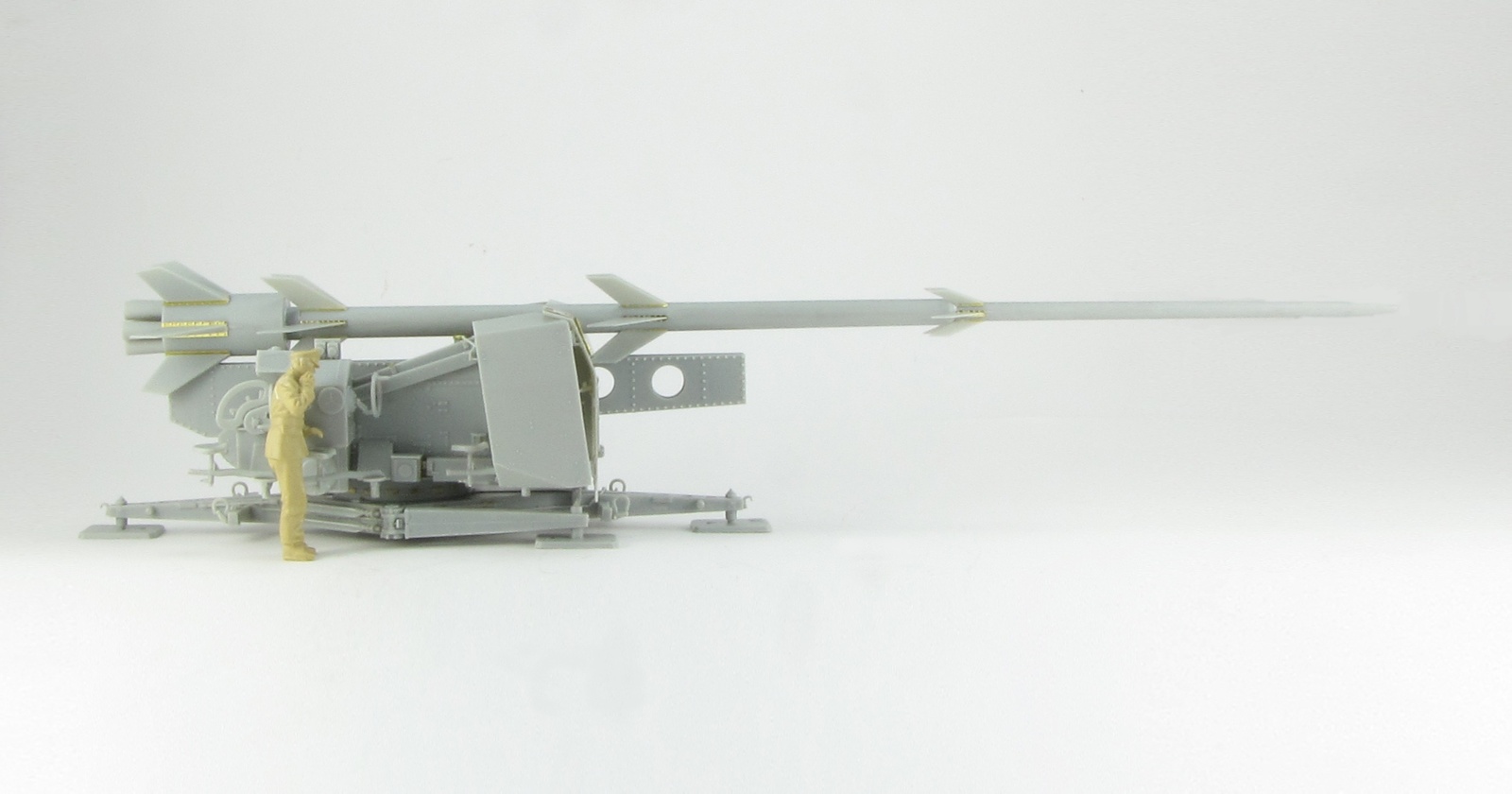
The Rheinbote was a four stage rocket developed by Rheinmetall Borsig in Germany, which was tested in 1944 and used in 1945. Measuring 11,4 meters long, it carried stabilizing fins on each stage.
It had a range of about 150km but no guidance, so it was launched in the direction of the target and with the estimated elevation for the distance desired.
Considering that its warhead was only 40kg, it is not strange that the project was cancelled due to its lack of destruction power and accuracy.
The Rheinbote was erected and launched from a FR-wagen, which was a modified version of the Meillerwagen used for the V-2. Assigned to Artillerie Abteilung 709, they were supplied only with four FR-wagen of the twelve intended. The rest seem to have used improvised versions of the Flak41 base, like the Rheintochter.
Unfortunately, I have not been able to find any photo supporting the use of this Flak41 base, only a blurry one that resembles this model but the rocket seems smaller and there are no shields on the mount.
The only known use in combat was against the harbour of Antwerp, in January 1945, and there is no record of its effectiveness. The project was cancelled in February, 1945.
First Impressions
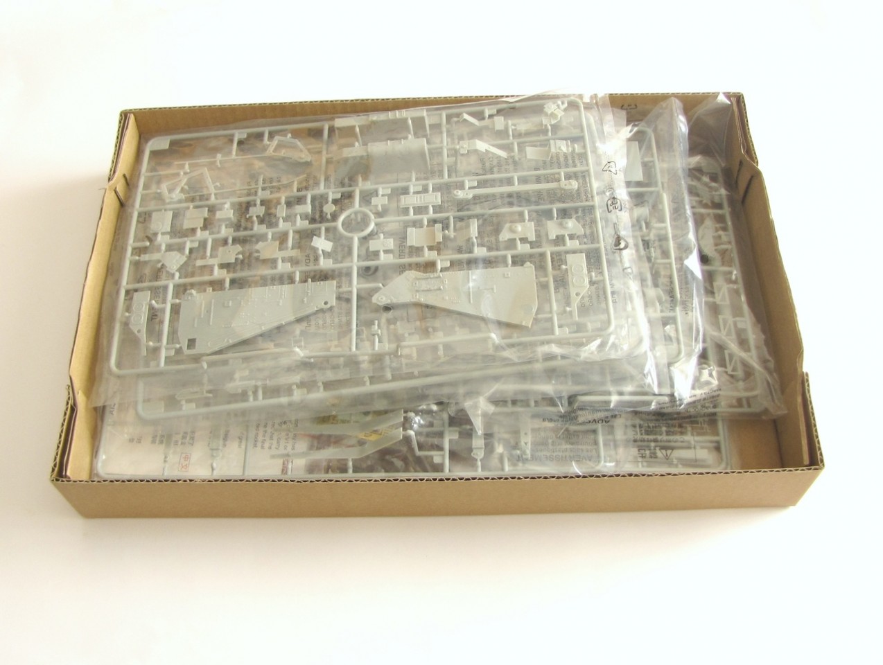
The kit comes in a good sized box, enough to contain the sprues without being crushed but without wasted room. Every sprue is sealed in a plastic bag, there are also two photo etch frets and an A4 poster of the box art.
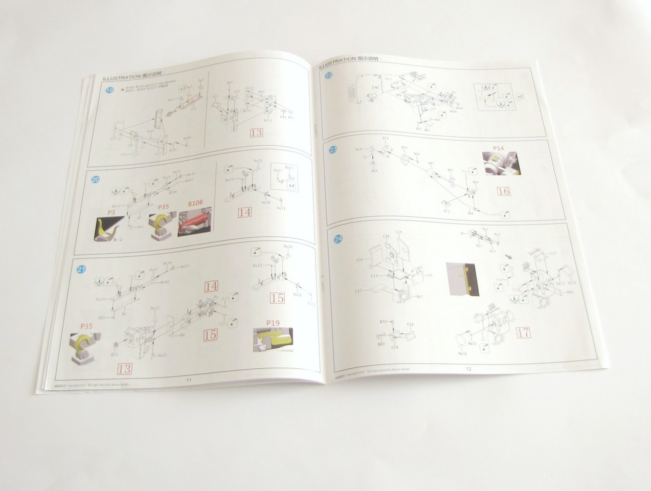
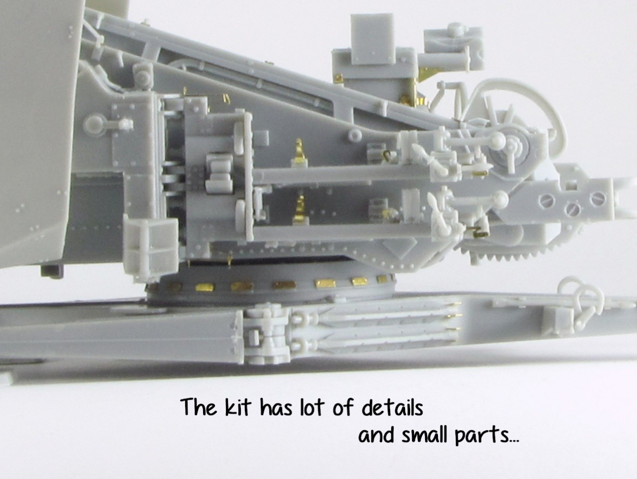
There is a large number of parts, and most of them will be used. The instructions are clear and offer exploded views when the details too small.
As usual in Bronco kits, at least from my experience, the detail is excellent and the fit equally impressive, however this comes at a cost: there are lots of tiny parts, and sometimes I see no point in splitting a part in two, as there is no real advantage in detail.
The plastic is nice, not too soft nor brittle but a sharp blade is needed, as often the parts are so delicate that some care is required for both detaching them from the sprue and cleaning the attachment point.
Another warning about cleaning. The fit is so good and precise that if you remove a bit more than needed when filing, it will produce a small gap when glued to the other part.
I have built the rocket in transport mode, probably the less common option. Apart from the indications on the instructions, there are a couple more of specific features of this mode that I will detail.
Building the kit
The process starts with the base, in my case I glued the sides first to the top part (A1) instead of the bottom one. This mistake was at the end an advantage, as the sides were perfectly aligned with the top while a small gap was at the bottom, where is hidden.
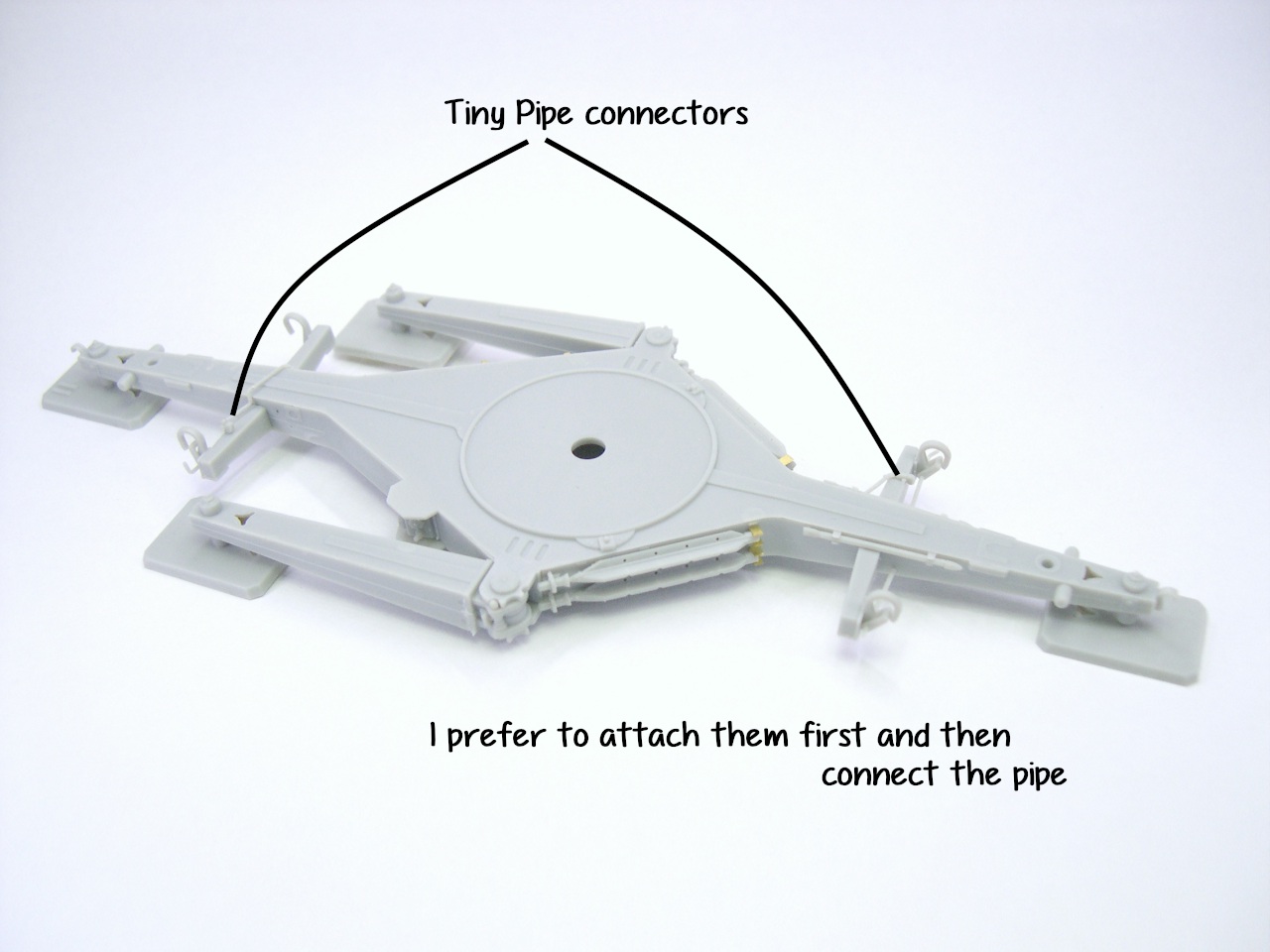
There is a pipe running along one side and attached to a couple of small connectors in the transporting arms, (A27 and A34). To ensure they end connected, I glued first the arms and attachments and afterwards added the pipe.
The legs can be left movable to show the rocket in firing or transport mode. However it only allows to delay the decision of how do you want to show it, as the shield must be glued either folded for transport or deployed. Moreover, the cables are fixed also and are different parts for each option. Therefore, if you already know how it is going to be, you can just fix all the parts.
Same is valid for the spikes that keep the base fixed to the ground (Db1).
Next steps are for the inner trunion, just note that the box B10 has the lid B53 not on the hollow part (as one may think) but on the front.
Attaching the PE cable strips Pa1/Pa3 at this stage makes no sense for me. Apart from making more difficult the join of the trunion walls later on, it will be broken for sure. So once you have fixed F31 and F32 to the trunion, then add them.
The rocket should be built then, but I see no advantage in having it built around my small workbench, so I left it until the end.
Several parts attached to the main walls of the trunion come then. I decided to attach only the ones on the inner sides, while the rest of components like fuse setter and controls will be added later.
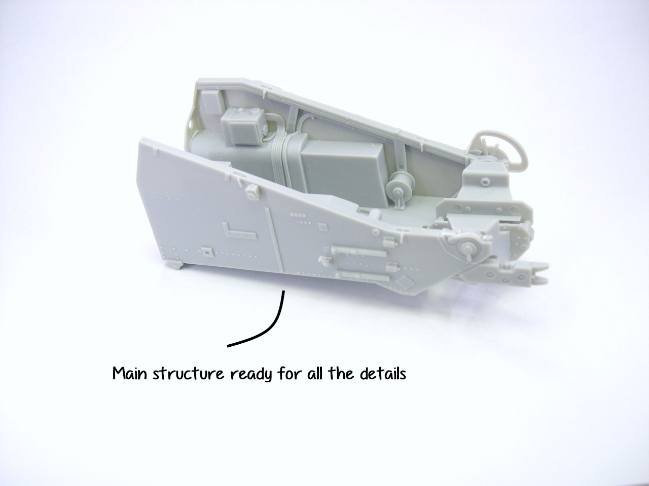
As there are a lot of delicate and tiny pieces, both in plastic and photoetch, I prefer to join the walls to the base and then start adding details.
This way, I can freely manipulate the walls until they fit all sides and front without risking to break anything.
I should have left out B19 until the cables Pa1 or Pa3 are in place, it is much easier. These photo etch strips will be shaped better if annealed, by the way.
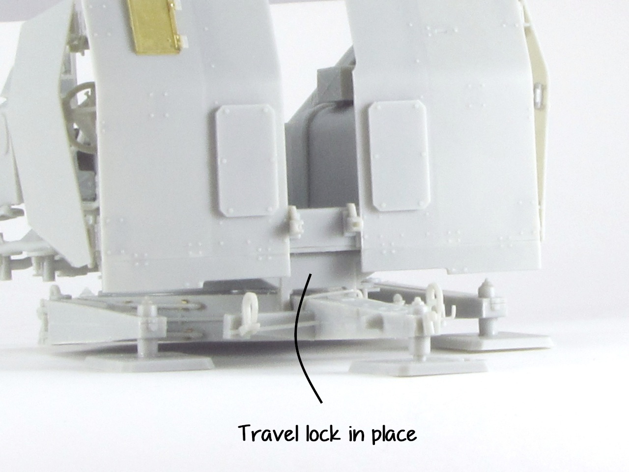
Before gluing these sides, I added the travel lock F34 between them. It is not mentioned on the instructions but it is logical to think that if the rest of the parts were retained, this should be kept as well. In fact, the painting guide shows it.
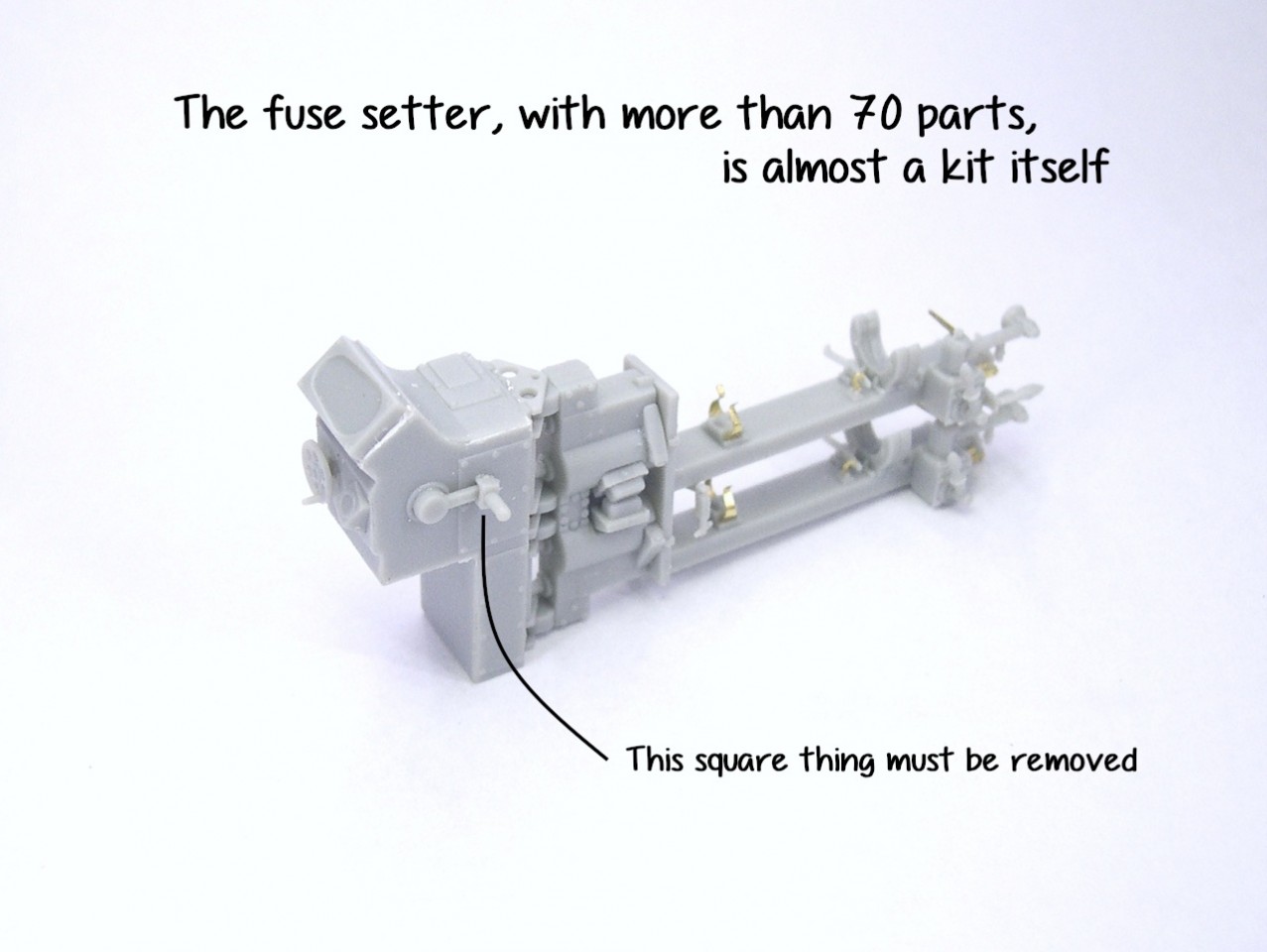
Once I have the main structure, I retake the suggested order and proceed with the fuse setter.
This is almost a small kit by itself, with over 70 parts spreading over four steps on the instructions. A good number of pars here are quite small.
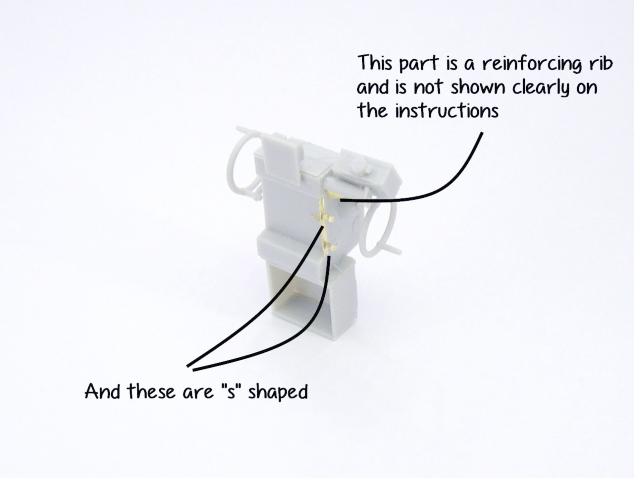
Again I prefer to attach all big parts and leave the photoetch at the end.
The detail is excellent as usual, so as the fit. Note that there is a mistake on the instructions, and PE part 47 should be 46. The foot rest B65 was folded for transport, so I softened the joint with liquid glue and slowly bent it to the desired shape.
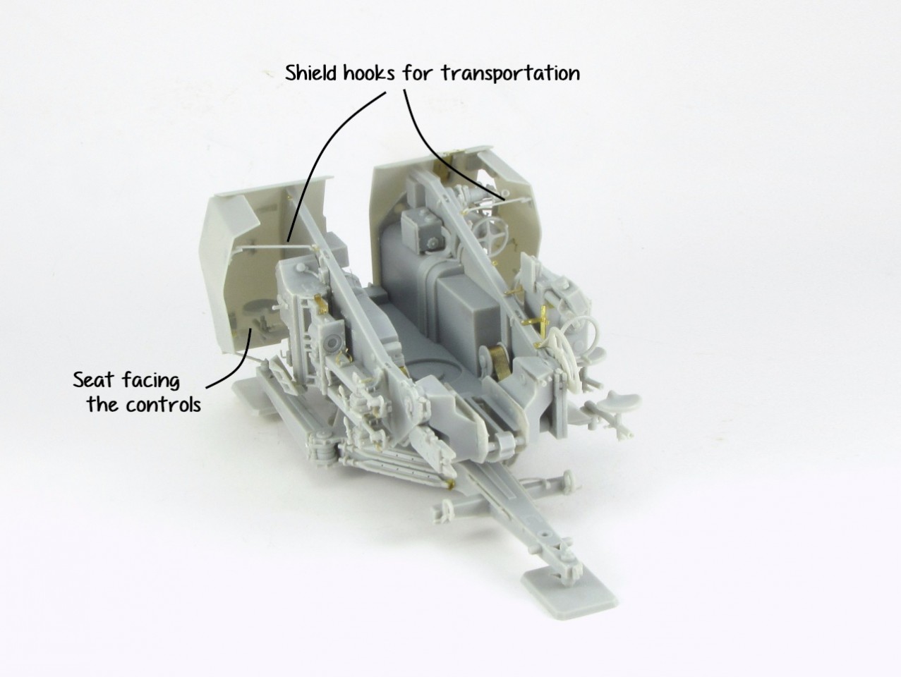
The seat in front of it should face the controls, and not the wall as the instructions say.
The hook Da7 is shown stored between both P31. This is valid for firing mode, for transport they were used to hold the sides.
Note that B84 is a cable and its terminator, attached to the wall. For a better positioning it is advisable to put it in place once the whole fuse setter is attached to the wall.
The controls on step 24 and 26 need a careful assembling to ensure there are no gaps. C25 is not clearly shown on the instructions, you can see where it goes on the attached photo. Same for P4.
P21 and P22 rest against the back of the controls, so I glued these sub-assemblies first and then added the photo etch to ensure it touches all surfaces.
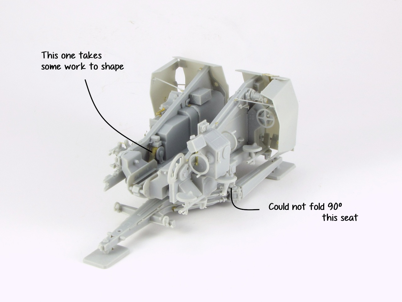
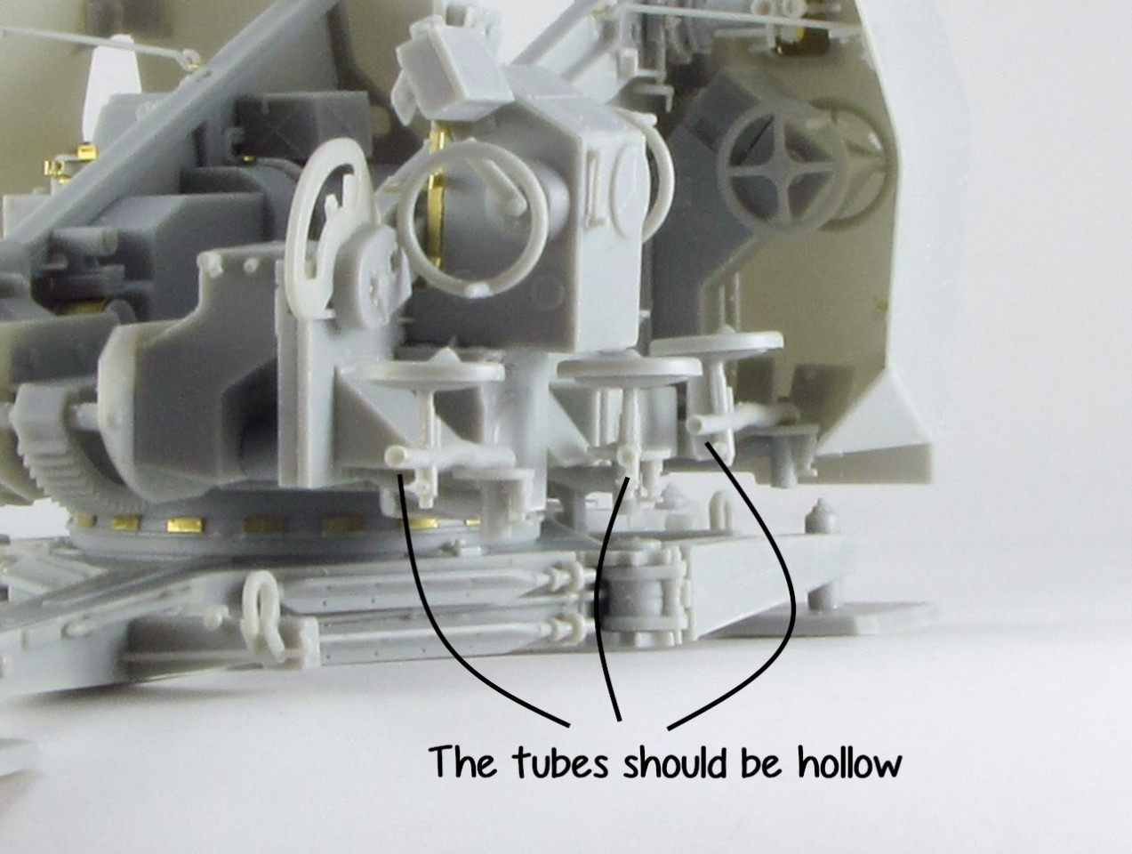
As for the seats, their arm Da24 was hollow so I drilled the outer end with the tip of a blade. This arm was welded to the round plate Da18, so if you want to show it folded for transport, instead of rotating the arm as per the instructions, you should rotate the whole plate, thus keeping visible its small holes. Note that at least in my case, the middle seat of the right side can not be folded 90º because the lower part of sub-assembly 17 blocks it.
The shields are another piece of art of this kit, moulded in thin plastic and carrying several tiny details. As usual I attached first all plastic parts and afterwards the delicate photo etch.
I had no clue about P24 and P8, and could not find a clear photo either so I removed the tab of P24, bent 90º P8 and glued it to the back.
Gluing the sides of the shields was a bit hard, the contact points are quite small (just the hinges) and the locking A28/29 seems to be slightly large. Perhaps it would be easier to attach it once the sides are in place, despite the difficult access.
Remember that if you want to show the sides folded in transport mode, the hooks Da7 are positioned from the trunion to Db14 on the shield. For me it was easier to glue first the part to the shield and while soft, use ciano to glue the other side with the little plate.
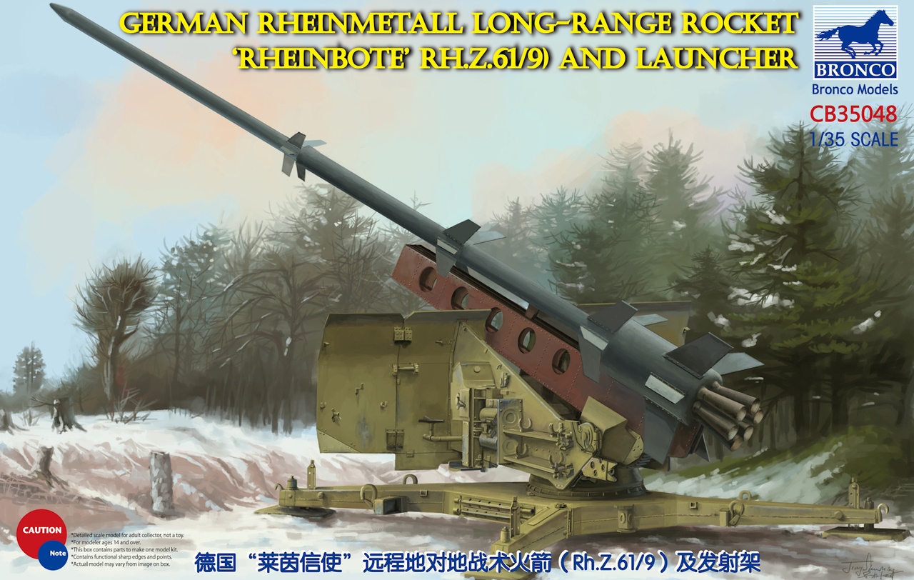
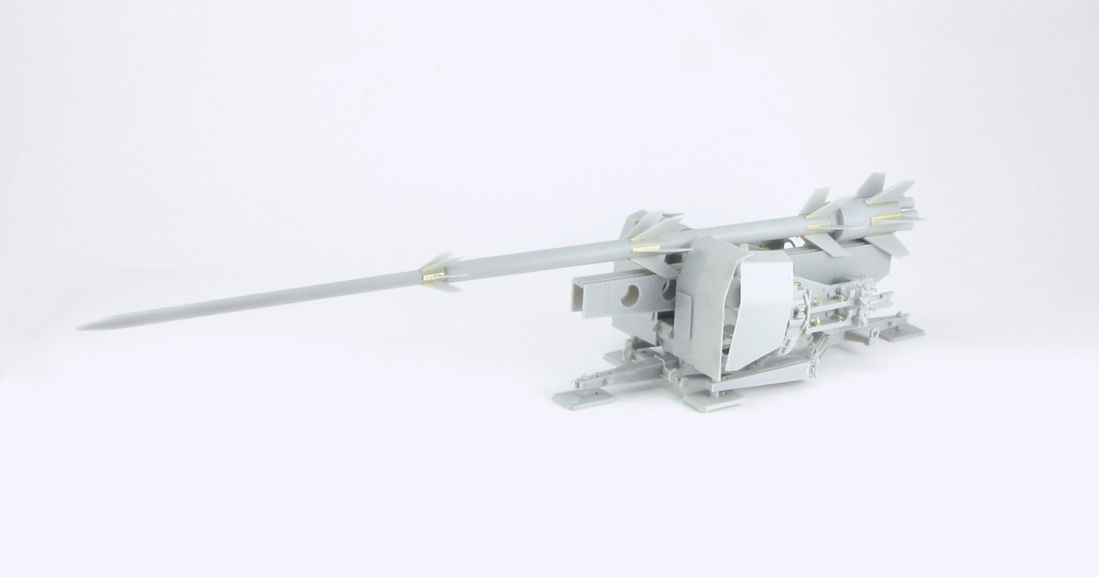
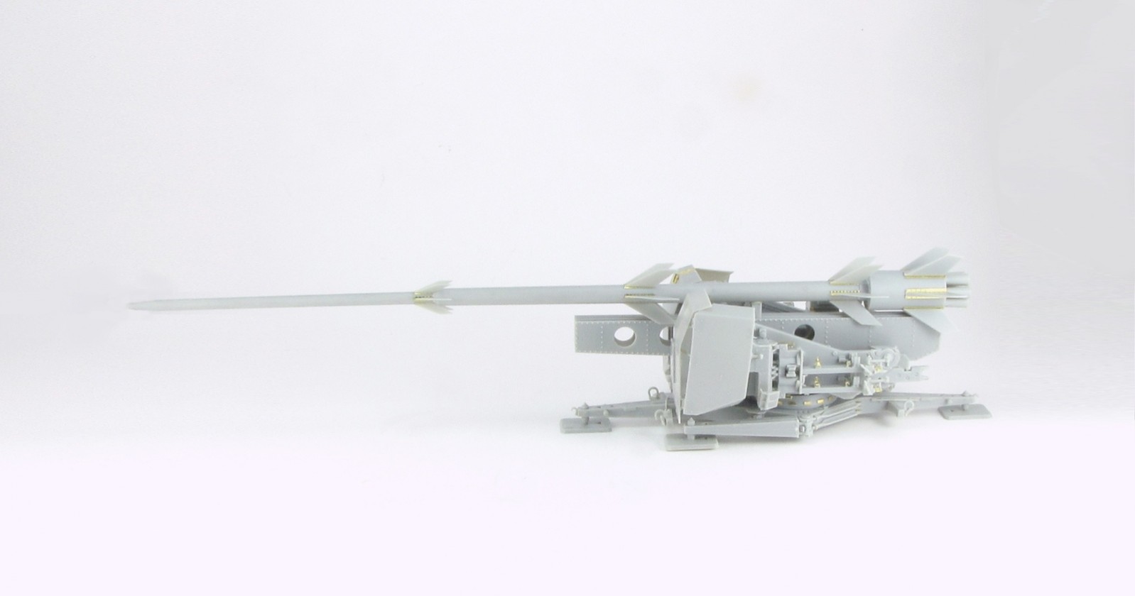
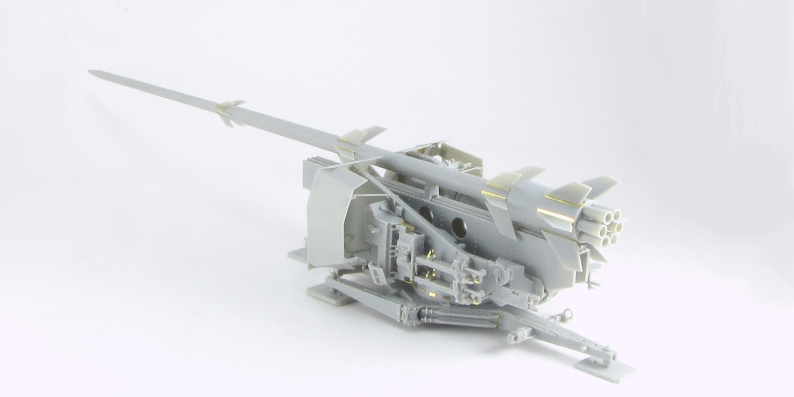
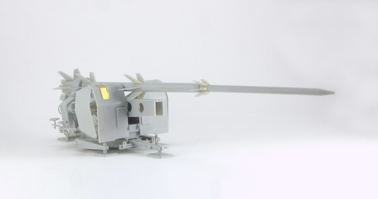
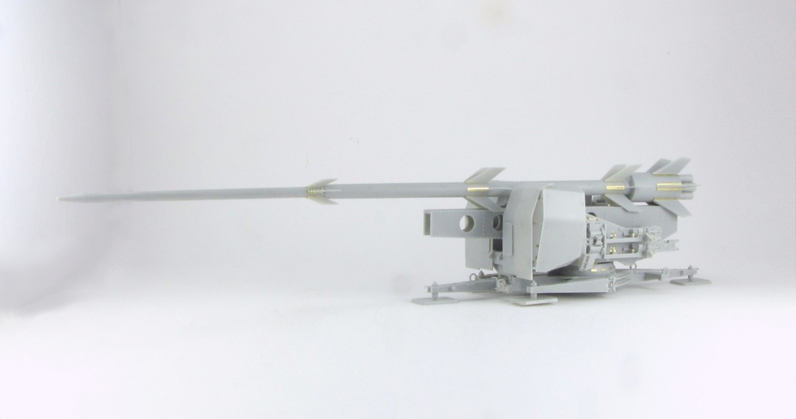
So at this point the whole base is done. It is time to work on the rocket. After considering the proposed sequence, again I decided to go my way and instead of assembling both halves first, I followed a more conventional approach of making each cylindrical section first and join them afterwards.
This required carefully alignment and left a couple of tiny gaps between sections. However it was easier to sand the longitudinal joints before gluing the stages.At the end it went fine but in this case I am not sure whether it is better than the instructions procedure.
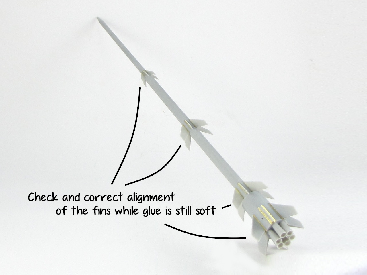
The fins fit fairly well and can be fixed with styrene glue. Good thing is that it allows time for careful alignment. I could not see any difference between fins on each stage, but they carry different part numbers... Anyway I followed the instructions. Gluing them in pairs of the same number makes the alignment easier,as they have to form a straight line.
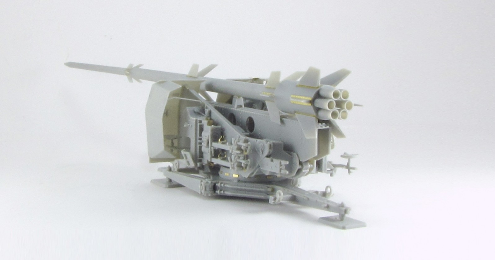
For easier painting I have finished here the construction. This leaves me with three big sub-assemblies: the whole base, the beam and the rocket.
In time it became painted by my own hand.... And this story shall also be told.
Conclusion
As you can expect from Bronco, this is an excellent model with practically no faults, great fit of parts and impressive detail. On the other hand, its construction requires time to clean a lot of small parts and carefully positioning them. I have often changed the instructions sequence but this is my personal preference rather than a problem.
Other than drilling the seat tubes, correcting the left seat position and adding the travel lock, anything else is needed to finish a great looking model.
I have enjoyed building it and can only recommend it to anyone who wants to have a Rheinbote in his collection.
SUMMARY
Highs: Excellent detail and fit. Unusual subject.Lows: Overengineering in some areas, with parts unnecessarily broken down.Verdict: A highly recommended model, although requires some work due to the number and size of parts.
Our Thanks to Bronco Models! This item was provided by them for the purpose of having it reviewed on this KitMaker Network site. If you would like your kit, book, or product reviewed, please contact us.
About Carlos Martin (varanusk) FROM: SANTA CRUZ DE TENERIFE, SPAIN / ESPAñA
My main interest is German vehicles and guns, and I like spending time researching the vehicle and the options for the camo once I have chosen a subject. Sometimes I go for specific and rare vehicles, of which only two or three photos are known so it takes me a lot of time to figure how everything w...
Thanks, Carlos, for the detailed information.
Very helpfull for my own build.
Two questions remain:
First. I presume that the rocket was not in place during transport. Correct?
Second. Since the overall transport weight seems to be not too much, which tractor was used? Would a Mercedes truck or the Hanomag tractor be an option?
Your input would be helpful since hardly anything about the organisation of these 'batteries' (?) can be found.
I know a few were used from the centre of The Netherlands to hit Antwerpen, but that is all I found.
Enjoy the weekend.
Hello Paul,
Glad you liked it!
According to the instructions there was a transport mode, side shields folded and rocket horizontal but I am not sure.
If you can read German, this is by far the best online reference:
LINK
Google translate does a decent job to get the general view of the text but not enough to understand clearly about the transportation and other points.
I have to disagree with you regarding the weight... the rocket alone was 1.650kg and a Flak41 -including the gun- was almost 8.000kg
In any case, it is specified that it was towed by an Sd.Kfz. 8 (plus several supporting trucks and vehicles).
I would like to hear your experience when building yours, so as seeing it finished!
Sorry did hit the enter to soon And Paul the rockets were fired from a area near Nunspeet. But they did use a Meillerwagen for the Launching to Antwerp. the carriage of the Bronco model is only used at LEBA in Polen. the rocket was tested there and also the carriage was only used there. a new development but to late for winning the war. You can read the story in a number of After the Battle no 114. Greetings Bert


Comments