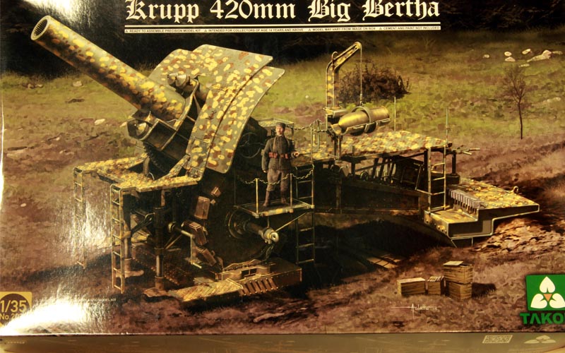
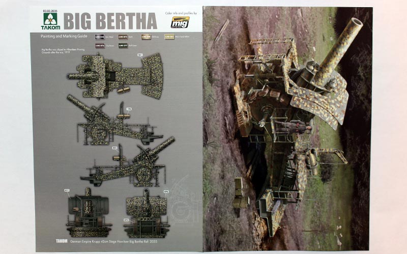
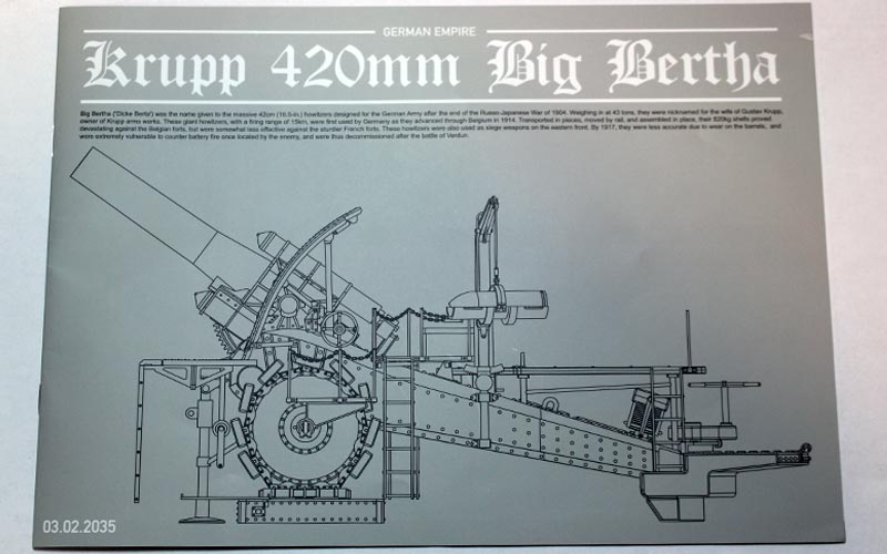
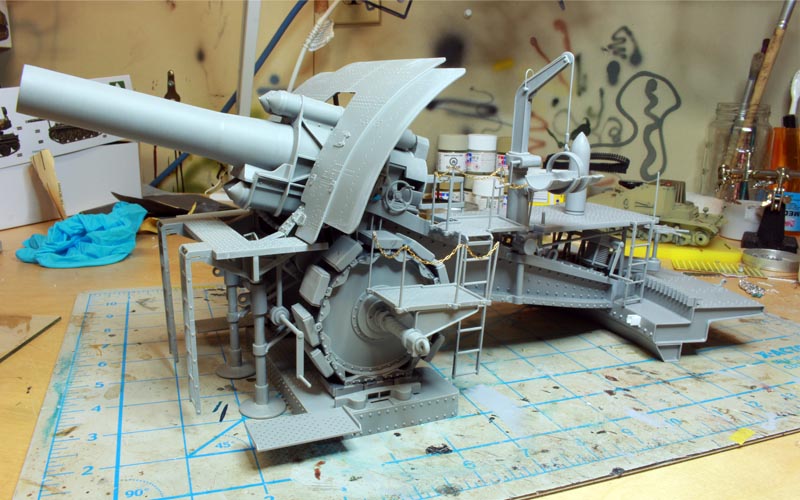
Big Bertha (Dicke Berta) was the name given to the massive 42cm (16.5-in.) howitzers designed for the German Army after the end of the Russo-Japanese War of 1904. Weighing in at 43 tons, they were nicknamed for the wife of Gustav Krupp, owner of the Krupp arms works. These giant howitzers, with a firing range of 15km, were first used by Germany as they advanced through Belgium in 1914. Transported in pieces, moved by rail, and assembled in place, their 820 kg shells proved devastating against the Belgian forts, but were somewhat less effective against the sturdier French forts. These howitzers were also used as siege weapons on the eastern front. By 1917, they were less accurate due to wear on the barrels, and were extremely vulnerable to counter battery fire once located by the enemy, and were thus decommissioned after the battle of Verdun.
Taken from the instruction booklet cover.
Takom recently released a 1/35 scale model of this large artillery piece, kit no. 2035.
the kit
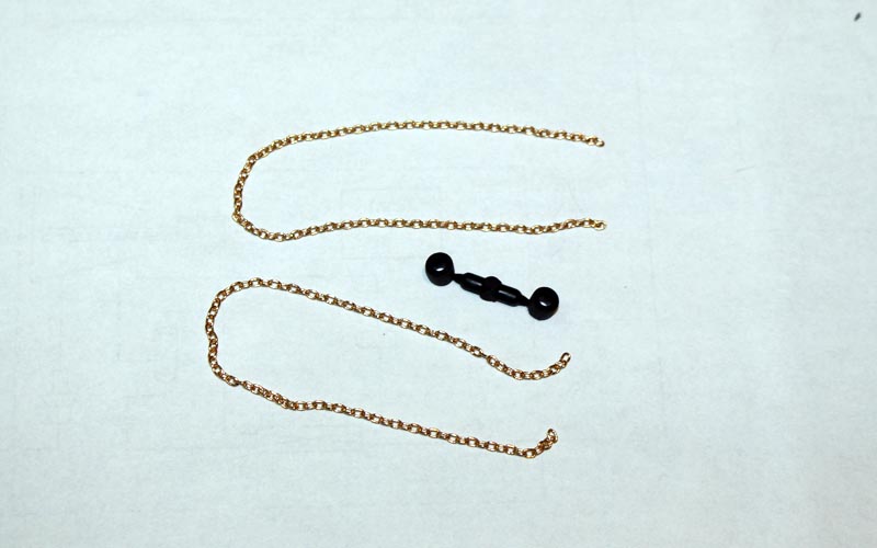
The kit comes in a large cardboard box with some beautiful artwork on the top depicting the piece in firing position, three paint schemes on one long side and kit contents on the other, along with pictures of Takoms Mark I and other howitzer kits. Inside you will find a total of 6 large parts sprues of parts, 2 chains and two soft poly caps. All of these are in separate polythene bags except the caps and chains, which were loose. There are a total of 257 parts, none particularly small, and some are very large. No clear parts, PE or any decals are provided.
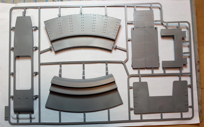
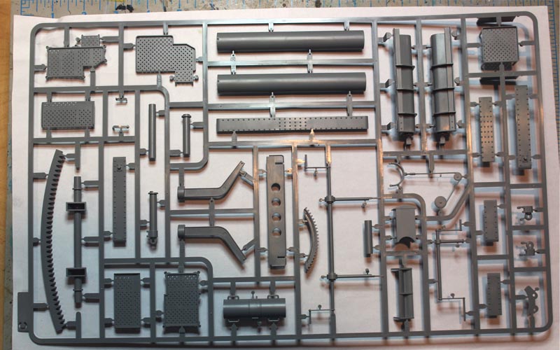
The kit is molded in grey plastic and the overall quality of the molding appears excellent, with sharp details, minimal mold lines, little to no flash and any ejector pin marks appear to be located where they will not be seen after assembly.
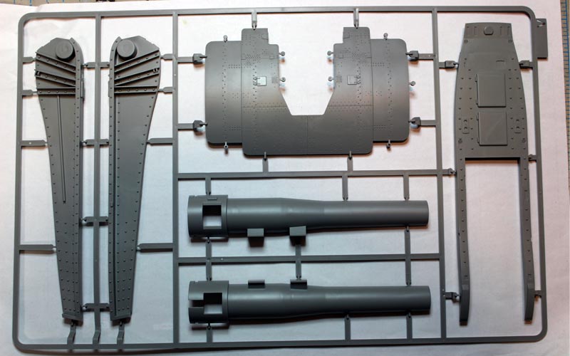
Sprue A, carries the sides and top of the gun carriage, the main splinter shield and the two-piece breech assembly.
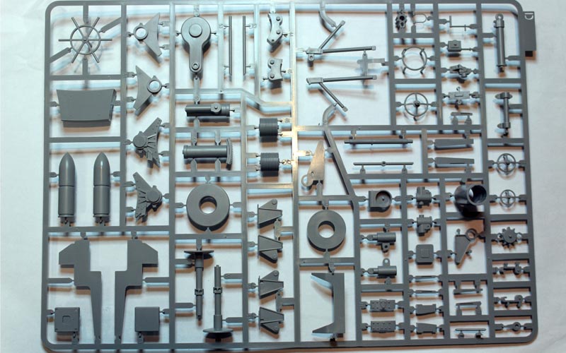
Sprues C and D hold numerous detail parts for the carriage and the gun itself, one of the shells, a two piece barrel and a single piece section of barrel complete with rifling.
Sprue B holds remainder of the carriage, the spade, and the larger crew platform pieces.
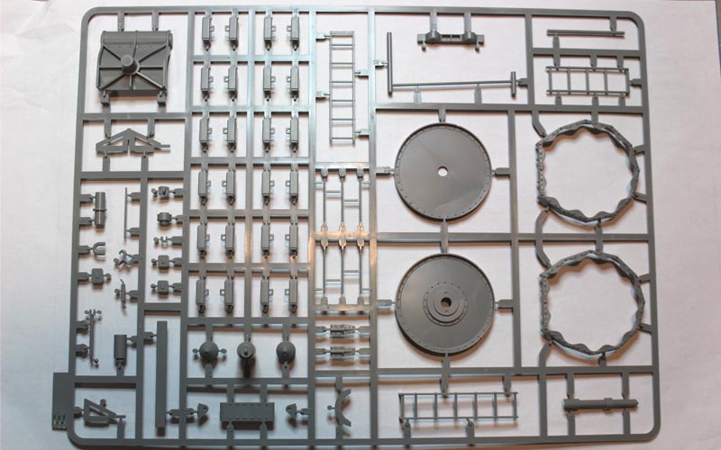
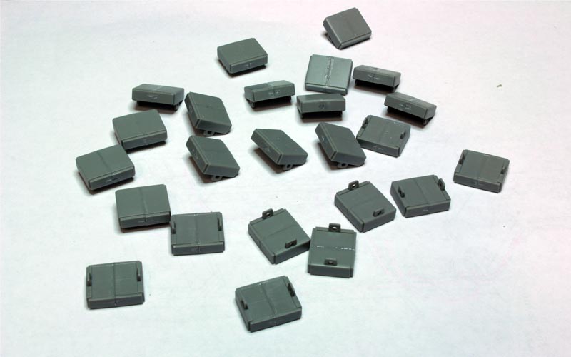
Sprue E , of which there are two provided is full of various detail bits the gun assembly, ladders and hand rails, plus the wheels and all of the blocks for the wheel belts.
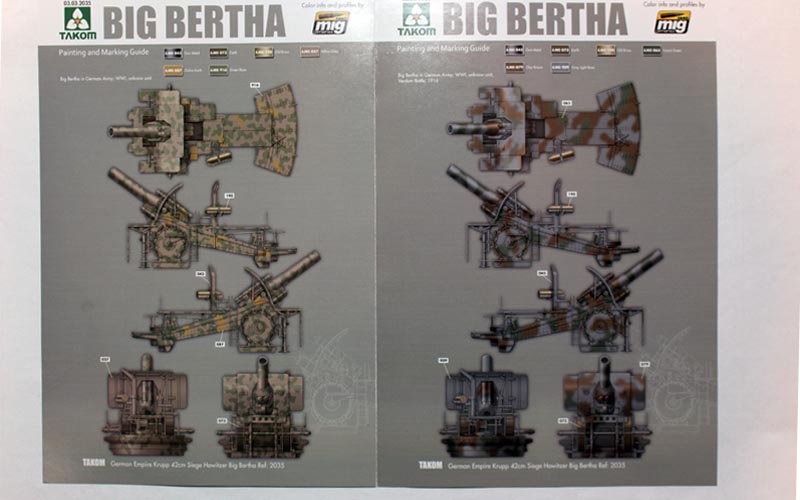
The instruction booklet is 14 pages in landscape format, covering 27 steps clearly illustrated with 3D CAD drawings. Three camouflage paint schemes are covered in the painting and marking manual , with all projections shown to ensure the builder can accurately reproduce the paint schemes. b>Takoms collaboration with Mig Jimenez is obvious as all colour callouts are Mig colours.
The Build
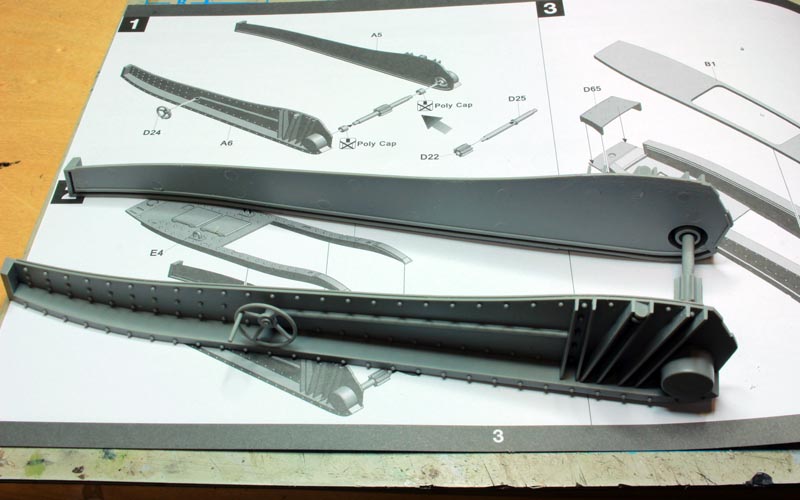
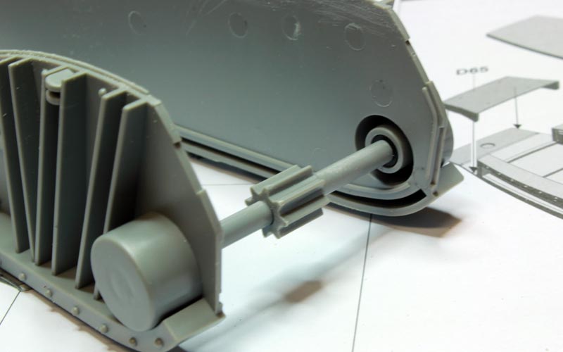
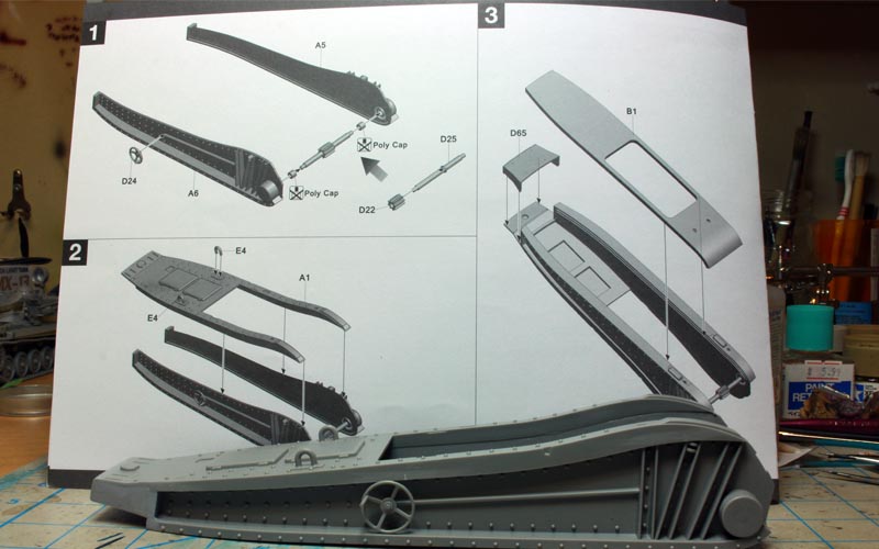
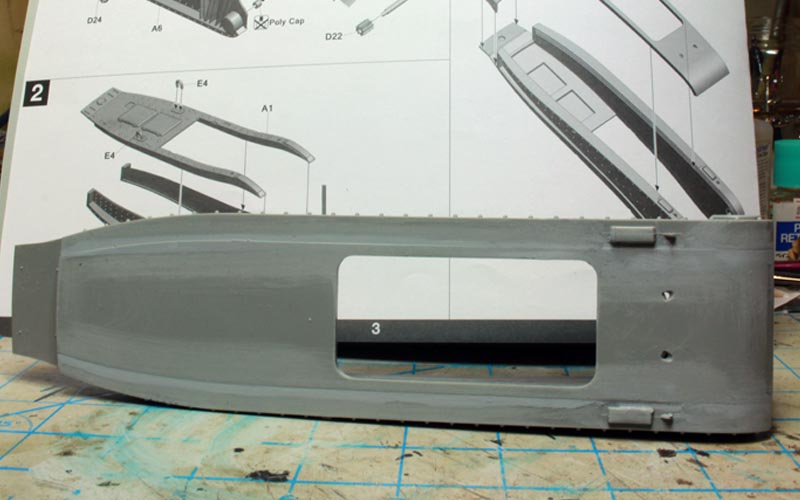
STEPS 1 to 3
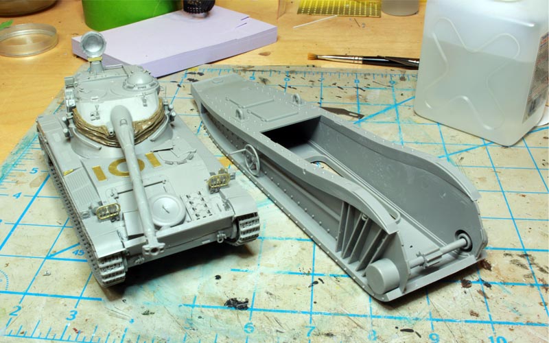
Construction begins with the gun carriage. This is constructed from some very large moldings and care has to be taken to make sure all the pieces are correctly aligned in order to minimize filling of seams. It took some fiddling and patient adjusting (with obligatory muttering and sticking of tongue out of mouth) to make sure the top and bottom pieces A1 and B1 aligned properly with the two carriage sides A5 and A6. There are no locating pins, just some shallow grooves that dont really do anything to assist in keeping everything aligned. I believe the parts were slightly warped as well, a result of being such large mouldings. Rubber bands and clamps were used to keep everything aligned until dry and then filling of seams inside and out was carried out.
The two poly caps are used in this first step to secure the elevation gear axle to the carriage. This allows the gear to rotate, theoretically allowing you to adjust the howitzer elevation after the model is completed.
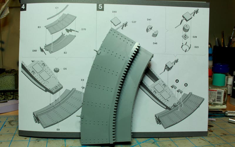
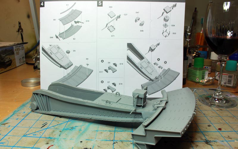
STEPS 4 & 5
This involves the assembly of the massive spade. The upper and lower plates of the spade are again quite large mouldings but fit together quite nicely. There are tiny locating pins and these are easily removed when you are cleaning up the sprue attachment tabs if you are not careful! Not that it really matters, I found the locating pins very small compared to the holes they were meant for, so there was a lot of slop in the fit and I couldnt rely on them to ensure proper alignment anyway. The traversing rack gear is attached, and I thought the instructions werent very clear as to how it is attached to the spade, there is a shallow lip it attaches to that is not clearly identified in the instructions and I made sure to dry fit it with the carriage and traverse pinion to make sure I had everything in the proper place.
The kit does not provide the full depth of the spade meaning that there is actually a lot more underground than what is provided in the kit, so it is not completely accurate for a standalone shelf display, but it is meant to be depicted as in a firing position so most people wont care. In any case, it wouldnt be too difficult to scratch build the missing part of the spade if its something that nags at you.
The carriage is then attached to the spade, and here we have four again very tiny locating pins matched to four holes on the spade to ensure alignment. The holes for these were more properly sized, giving positive alignment, although they are quite shallow and it is easy to disturb the alignment if you bump it while the glue is drying, or even if you simply set it down on your workbench. Clamps are recommended to keep everything aligned until dry. The pinion for the traverse rack is also added here.
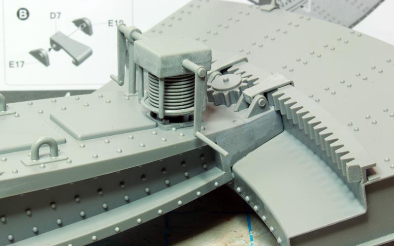
The hand winch for the munitions hoist is assembled and attached to the rear of the carriage along with the spade retainers. These all fit together very nicely with no issues whatsoever.
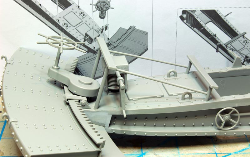
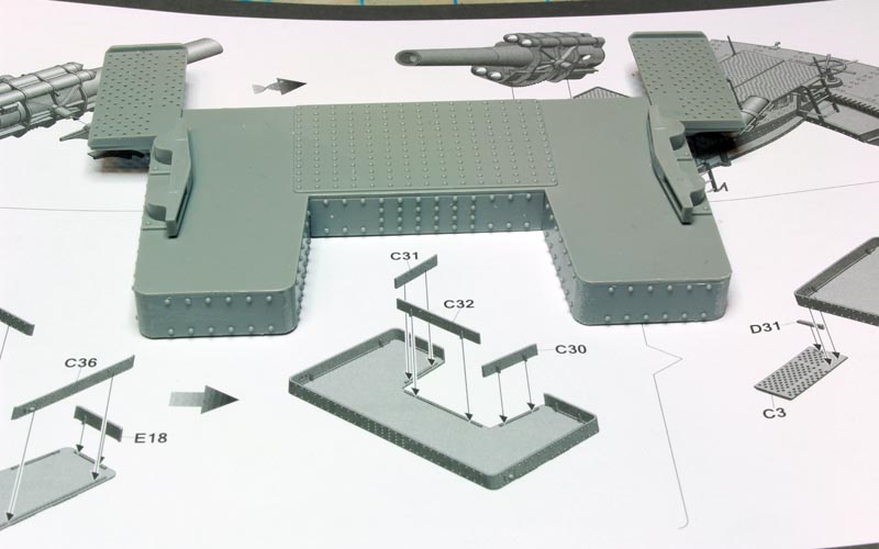
STEPS 6 & 7
The traversing mechanism is now added along with supports for the various crew platforms and the munitions hoist. I am not a big fan of the way Takom did this part of the model. The numerous cantilevers for the smaller platforms D13, D18 & D19 are all set in fairly loosey-goosey slots, and because you dont have the forward outriggers built and attached yet, these cantilevers will most likely end up misaligned. I recommend not installing these parts until after step 12 when the forward crew platform and elevation outriggers are installed so the cantilevers can be properly adjusted to provide level platforms. I ended up cutting them off and repositioning after step 12.
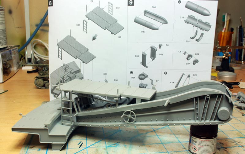
STEP 8
This is the large rear crew platform. It is a large single moulding with nice detail. The two ladders need some tedious mould seam cleanup but other than that everything goes together quite well except for some fiddling to get the platform to line up properly on the supports installed in step 6. You will probably want to have the platform ready when you install those supports so you can make sure everything lines up properly and make adjustments before the glue dries. I would also suggest leaving off the two E9 parts, these are fairly delicate poles that stick up from the rear of the platform and are easy to break off. Put them on last before painting!
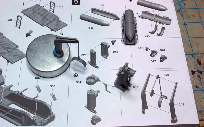
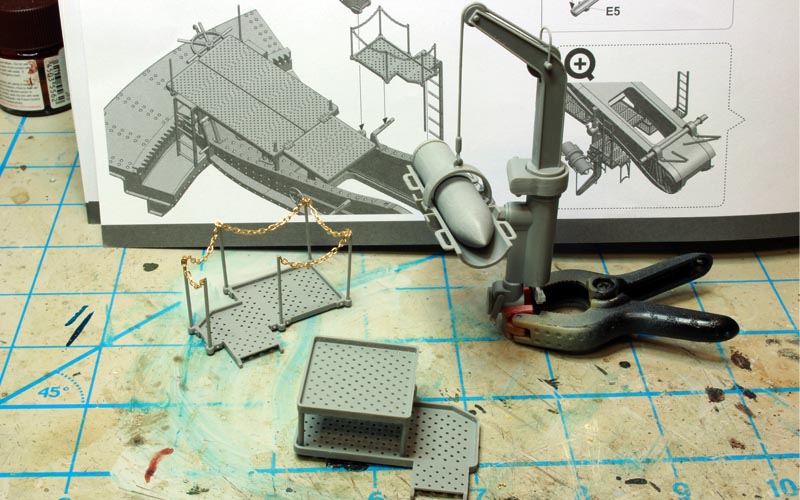
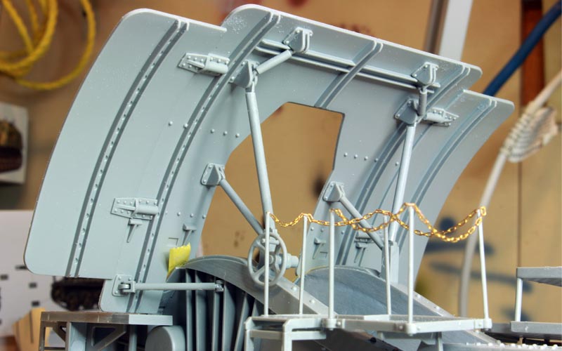
STEPS 9 & 10
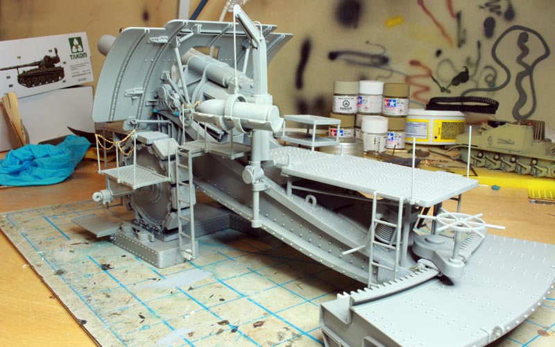
This entails the assembly of the single howitzer shell provided along with the munitions hoist, shell cradle, and hoist access platform. The hoist and shell assembly proceeds without drama and only some minor filling and mould seam removal. The hoist pulleys are molded with the cable as one piece, so some detail is missing here, this is something a lot of builders may want to replace with something more detailed. The hoist access platform is where the first piece of brass chain is used as the safety chain. The platform poles E27 are provided with small notches at the top to allow the chain to be hooked on, but it is a little tricky to get everything to line up well. I also thought the chain provided was too large to be in proper scale so I replaced the kit supplied chain with some smaller link chain I had on hand. I did not glue on the hoist to reduce the chance of damage as well as make painting easier.
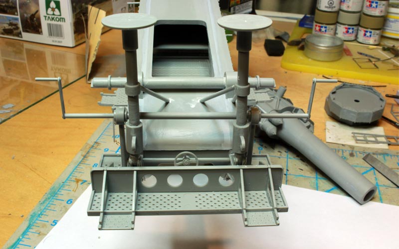
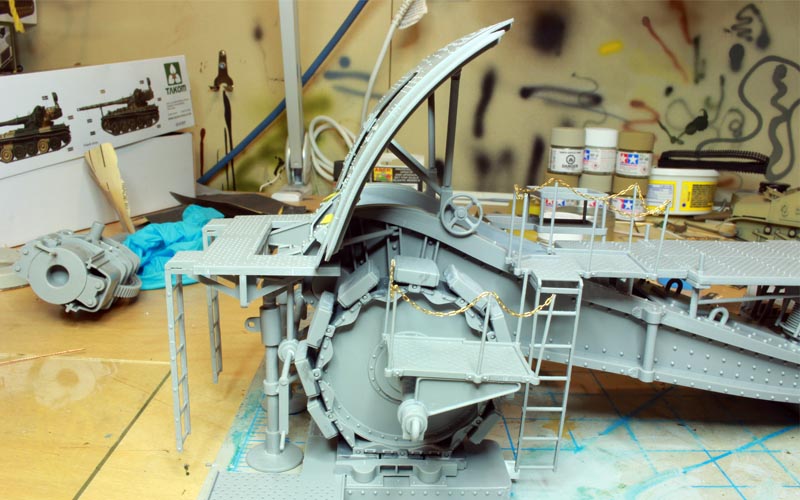
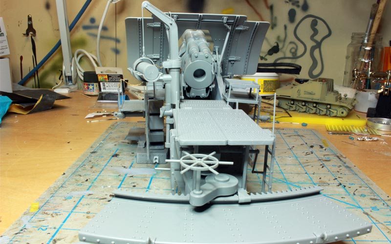
STEPS 11 & 12
Here we add another platform on the other side of the gun carriage, the axles for the wheels and then assemble the front platform and elevation outriggers. I ran into some problems with this small platform and it ended up not being level as you can see in the pictures, so I will be going back and making some adjustments before paint.
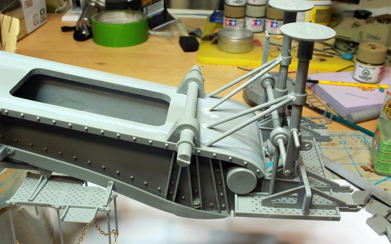
The front elevation outriggers go together quite well, again some minor filling and sanding is required, nothing major, but care is required to make sure everything lines up properly. The support stiffeners under the platform fall together nice and slick and the legs are added followed by the coarse elevation adjustment handwheel and ladders. When this assembly is dry you mate it to the front of the carriage. There are four braces D52, D53 and E38 (2) that go from the underside of the carriage to notches in the elevation legs. I found that one side fit perfectly but on the other side they were a tad short and would have resulted in the leg being crooked if I slotted them fully into the provided holes. Im not sure if this is a design/moulding flaw or I misaligned something along the way but a little bit of scrap plastic and filler solved the issue.
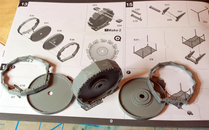
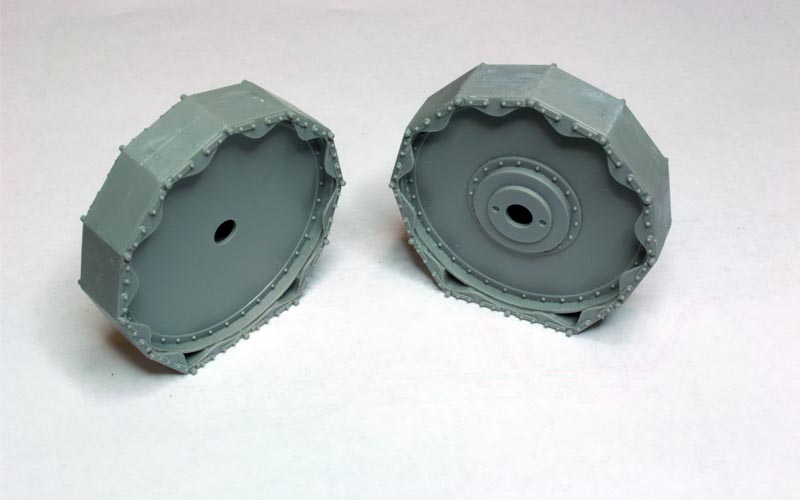
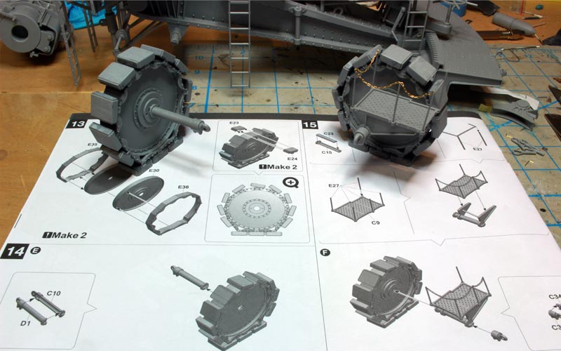
STEPS 13 to 16
Now it is on to the wheels and gunners platform. Each wheel is made up of four main pieces that fit together with the help of some small locating pins to ensure correct alignment, plus the 12 blocks for the wheel belts, each consisting of two halves. Once the wheel hubs and belts are together some minor sanding and filling was required to get rid of the joint seam, and then it was onto the blocks for the wheel belts. These each consist of two halves with a joint right across the face of the block. Again, there are two tiny locating pins on one half with two large locating holes for them on the other half, with the holes once again being significantly larger than the pins, so there is a lot of slop and you have to make sure you align then properly to minimize sanding and filling. I made sure I aligned the outer face that will be easily seen and a few scrubs with a fine file got rid of the joint. The inner face is another matter. Although it cant be easily seen on most, some will be visible and some filling and sanding to get rid of the joint and some flash is required. When the glue has dried, the wheel blocks snap onto the belts without the need of glue.
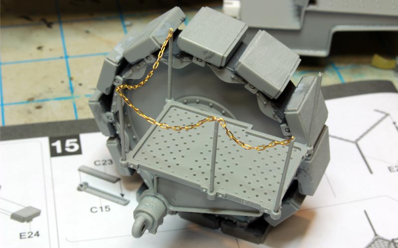
The axle extensions are then added and the gunners platform assembled and mounted on one wheel, with the second piece of safety chain installed. The wheels can then be installed on the carriage axles. I left them unglued for ease of painting, and I would recommend not gluing the axle extensions in place right away until you have ensure the alignment of the wheels as they are molded with a definite bottom and although the axles are keyed, there is still some slop and you could end up with the bottom of the wheel not being flat if you are not careful.
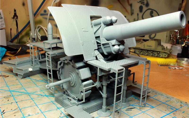
STEPS 17 & 18
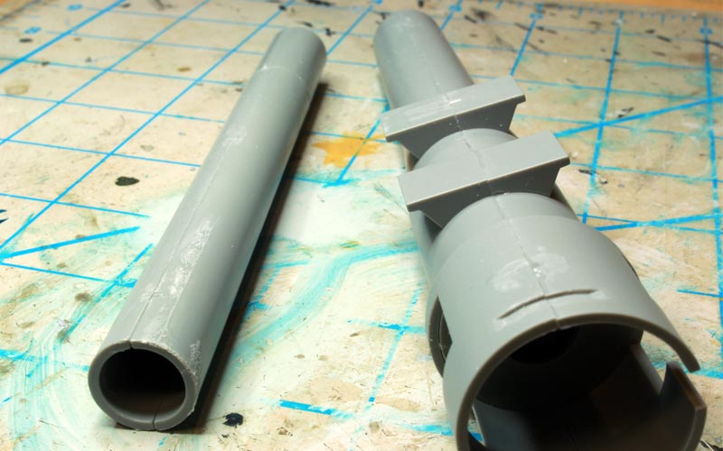
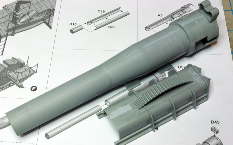
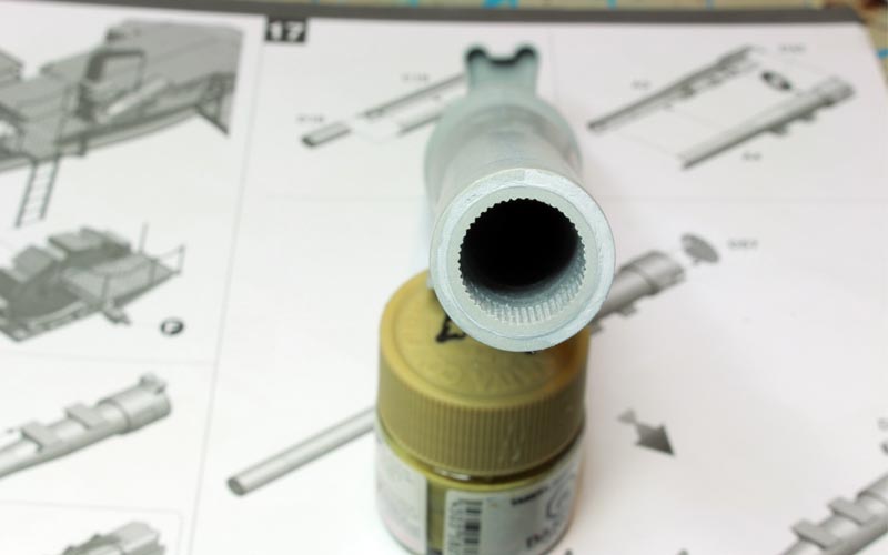
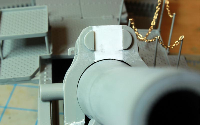
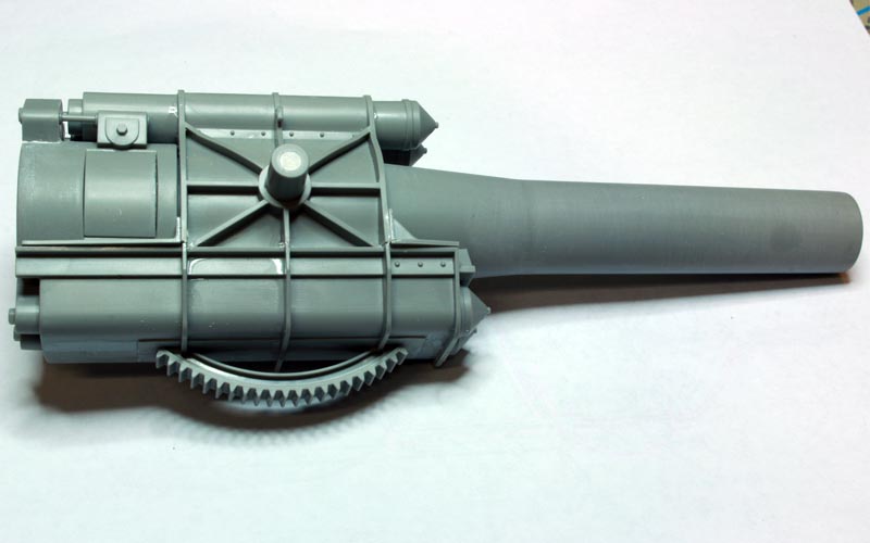
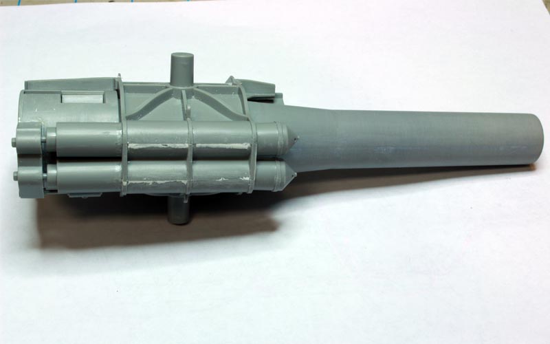
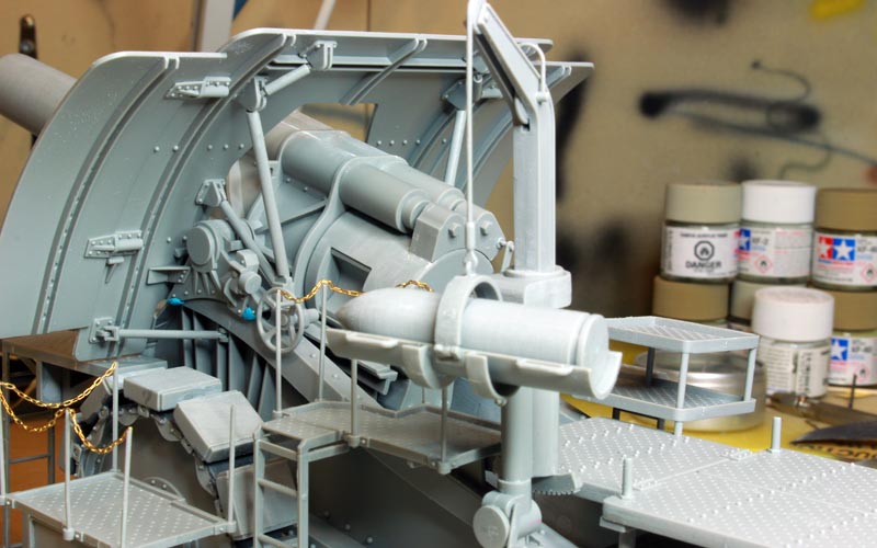
Now we are on to the part that goes boom. The barrel is a six piece affair, consisting of inner and outer barrels/breechblock to get the required thickness. As with any two piece barrel there will be some filling and sanding required to get rid of the joint seam, but they do fit together quite nicely and has provided the top inch or so of the inner barrel as a single piece moulding with some nice rifling detail.
The lower recoil cylinders fit together with some filling required to hide the seam, not that it will be very visible way at the bottom of the gun and slide on to the barrel/breechblock assembly but dont glue just yet!
STEPS 19 to 23
These steps cover the assembly upper recoil cylinders, barrel cradle, various breechblock detail bits and the pintles for the guns trunnions. Here a bit more filling is required as things dont seem to go together quite as well, but thats a relative thing, fit is still overall quite good and Im getting a bit nitpicky trying to find things to improve. The upper recoil cylinders are a bit fiddly to line up as they are moulded integrally with the cradle, with two sides and a top-middle piece that fits between, so getting everything to line up properly while the glue dries is tricky. When done, a fair amount of filling and sanding was required to get rid of the joint seam, and I found I had to use some 0.020 plasticard to level out the front so the cylinder caps would sit properly. It looks like Takom cast the center piece C24 just a tad too short.
The instructions would have you glue the pintles to the carriage now but I left them loose and just secured with bits of blue-tac to allow disassembly for painting.
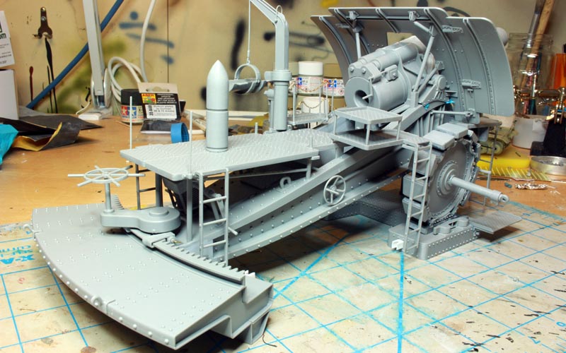
STEPS 24 & 25
Assembly of the foundation platform is straightforward and easy, everything fits together very well. Almost no filling or sanding is required if you take your time and are careful with alignment.
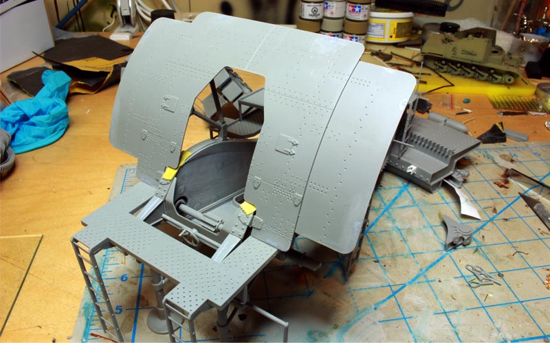
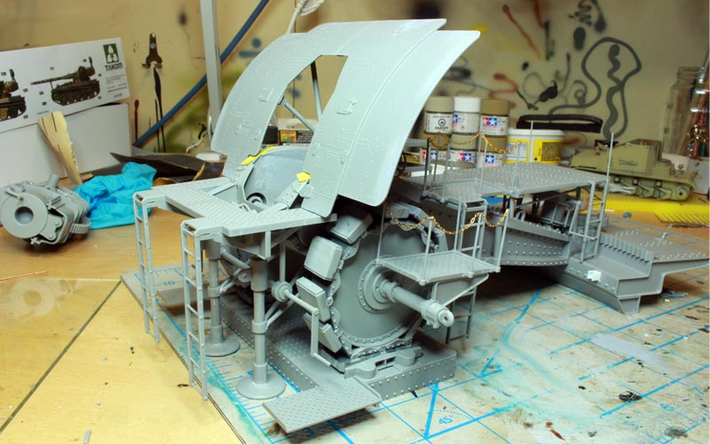
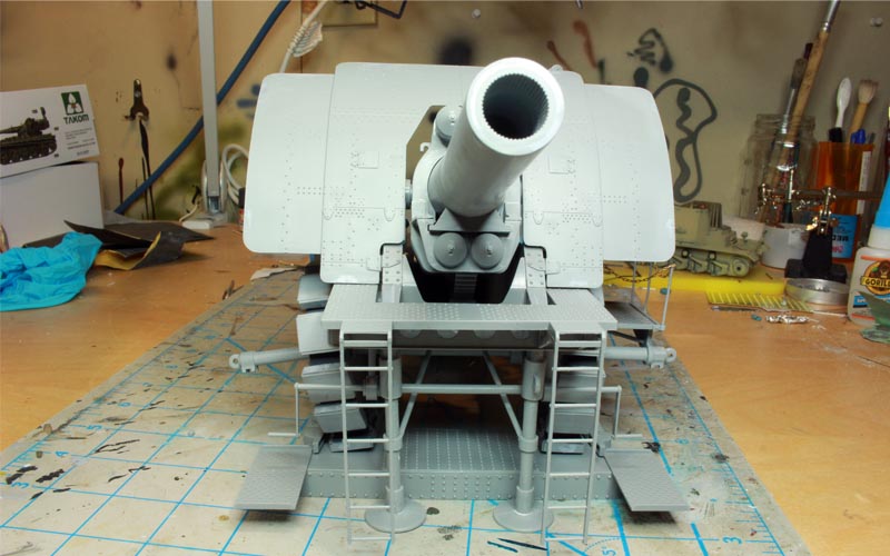
STEPS 26 & 27
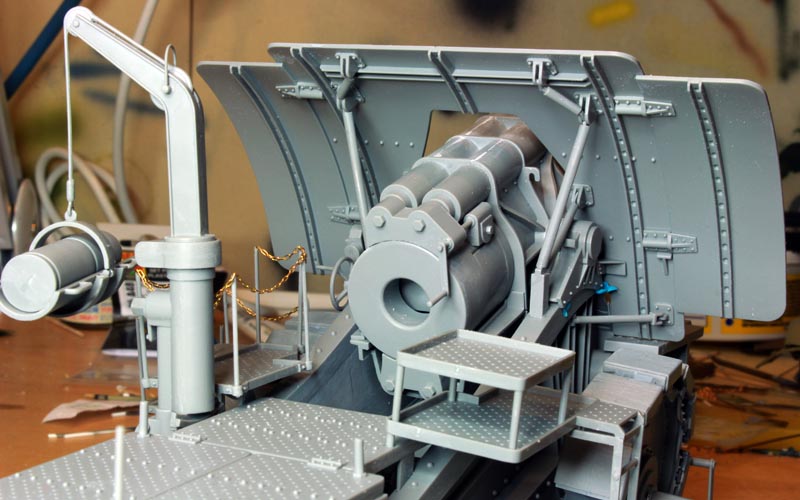
These steps are primarily concerned with the assembly and attachment of the splinter shield and the fine elevation hand wheel. The upper and lower splinter shield brackets are attached to the cradle and carriage first, but dont glue the lower ones (E2) in place, you will want to leave them loose to make sure you can line them up with their associated brackets on the shield when that is installed. For this I would recommend completing step 27 first so you have the completed splinter shield ready to go when attaching the brackets. The shield itself is a single piece with good rivet detail and there are 6 mounting points that line up beautifully with the brackets attached to the cradle. Again, I left this unglued to make painting easier.
Conclusion
This was my second experience with a Takom product and first time with an artillery piece of this magnitude (the only other artillery piece I have done was Tamiyas 25 pounder 30 years ago ) and I can say that once again I am quite pleased with what Takom has to offer here. The amount of detail, casting quality and fir of parts is for the most part excellent, with only a few minor instances of flash, and very minimal mould seams to clean up. There are a few issues as noted previously, and I did find the instructions a little vague at times. There are a few missing details that would have been nice to have seen in the kit, such as the shell rammer, aiming poles, pioneer tools and some addition brackets and pins but these are things I will add before painting (you can see some of them in Tobias5555s build of the same kit). Overall, it builds up to a truly impressive model and I feel Takom has done a wonderful job on this kit and highly recommend it to fans of large artillery pieces, just set aside a lot of space for it!
SUMMARY
Highs: Sharp detail, massive size, generally excellent fit.Lows: Only a few instances of minor fit issues, lacking a few details.Verdict: Overall and excellent kit that builds up into a very impressive model.
Our Thanks to Takom! This item was provided by them for the purpose of having it reviewed on this KitMaker Network site. If you would like your kit, book, or product reviewed, please contact us.
Colin started modelling with cars and planes as a young child then moved into armour by rebuilding his older brothers motorized Tamiya Tiger II and winning a model contest with it at age 12. He continued modelling into his teens until university and other distractions got in the way, resuming the...
Good review.
These guns were a major part of the Verdun battle (The Price of Glory is a superb account of the conflict), so I think a fire base with one would be an excellent subject matter.
The breech area is way over simplified and wrong. I completely redid that area. I too noticed the winch drum. That will be a total rebuild too.... But considering I never thought we would see this piece as a plastic kit I love it !
Love the fact that new kits like this are coming to market but you should check out some of the comments relative to kit accuracy that were posted to the Landships web site. The kit was based off of a 3D model from turbosquid and then slightly modified. Shame that so little additional research was conducted to make it right. While this is an impressive kit and made well, it seems that it is not very accurate. Happy Modeling
Excellent review Colin. Thank you again for taking on this review for me. This kit and the Riich Models Maschinengewehrwagen 36 If. 5 definitely went to the right guy.
Thanks again,
Randy
I don't believe there are any dedicated figure sets, yet, but there are some generic inf figures such as this: LINK , and this: LINK , and this: LINK , and this: LINK . All resin figures from Stalingrad.


Comments