Introduction
Smallest of Germanys unarmoured half-tracks of WW2, the Sd.Kfz.10 was developed by Demag to a requirement for a light cross-country vehicle with high road speed and the ability to tow light artillery and ammunition trailers. By 1945, around 14,000 units of the D7 production vehicle had been delivered by several firms in a multitude of configurations, with the underlying components also forming the basis of the armoured Sd.Kfz.250, so it is a design of some significance.
Dragon have released a number of kits based on the Sd.Kfz.10 since 2011, including: armoured and unarmoured 10/5s mounting 2cm Flak 38s, 10/4 with Flak 30, the Cyber Hobby 3.7cm PaK mount, a semi-armoured mounting for a 5cm PaK38, more recently an Ausf.B 1942 Production vehicle, and the no longer produced Cyber Hobby Ausf.A 1940 Production kit. Here we have an Ausf.A boxed with a 5cm PaK 38; below Ill describe what that means and then look at how the half-track itself builds up.
Contents
The box brings together sprues from previous kits, and though I wont try to identify all the original source kits, I convinced myself that the statement on Dragons website that the kit does not feature any newly tooled parts is accurate:
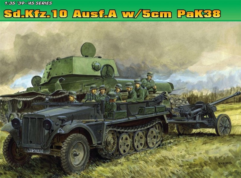
- Sprue A (black) tagged with Sd.Kfz.10/05, contains much of the front bodywork and has the largest number of unused components (photo 1)
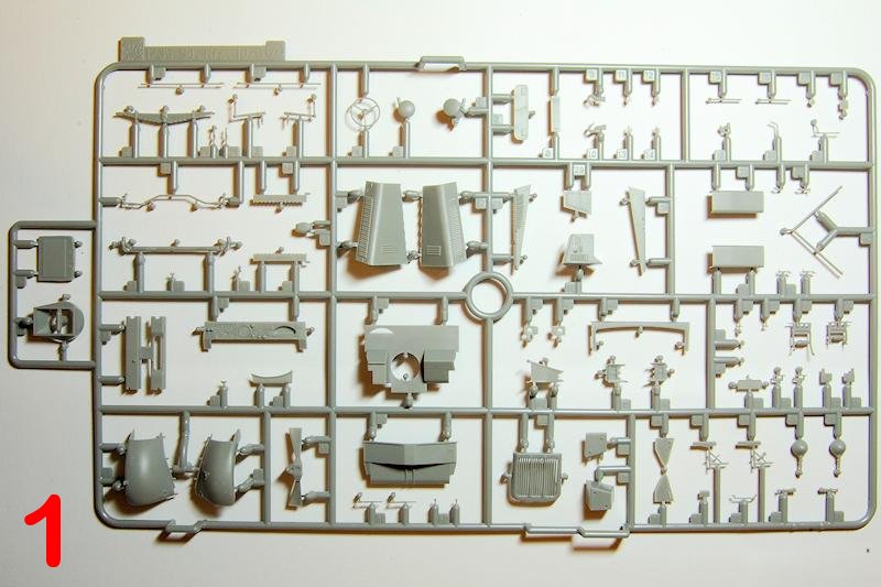
- Sprue B (black) tagged Sd.Kfz.10/05, suspension members, engine, transmission and the two piece front tyres and wheels (photo 2)
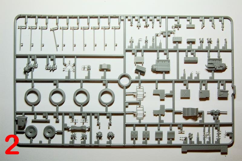
- Sprue D tagged Sd.Kfz.10/05, rear bodywork, tools and small details (photo 3)
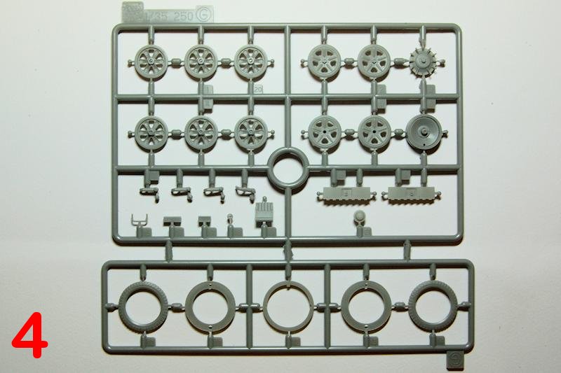
- Sprue G (black) 3 off, tagged Sd.Kfz.250, wheels for the tracked units and front wheels plus five part road tyres (photo 4)
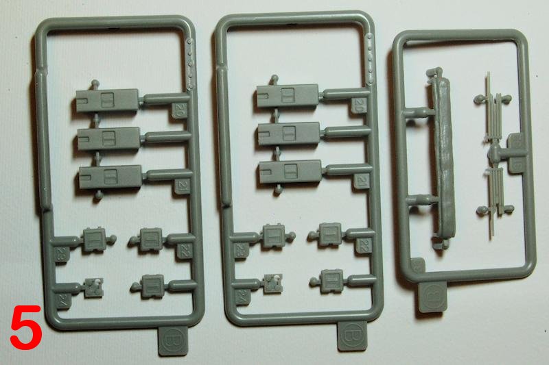
- Sprue B (blue) 1 off, folded canvas and folded arms for the stowed roof (photo 5)
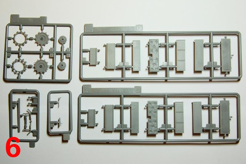
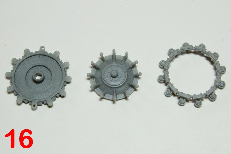
- Sprue H inners and outers of the drive sprockets only (photo 6)
- Sprue F 2 off, rear stowage bins/seats (photo 6)
- Sprue B (blue) 2 off, six ammunition boxes (from Cyber Hobby 6720 and Dragon 6719) (photo 6)
- Sprue G (blue) two separate tiny sprues: rear fittings and wing mirror (photo 6)
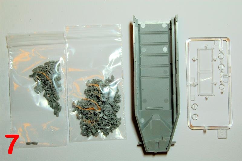
- N 96 off two part magic track links (photo 7)
- Sprue V clear parts for windscreen, lamps and mirror (photo 7)
- X the one piece vehicle hull (photo 7)
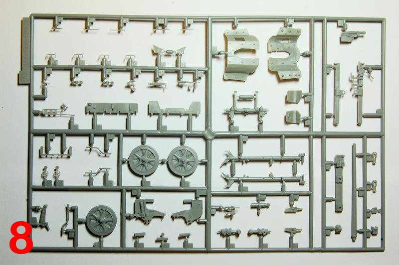
- Sprue A the entire 5cm PaK 38 (from Dragon 6444 and 6684) (photo 8)
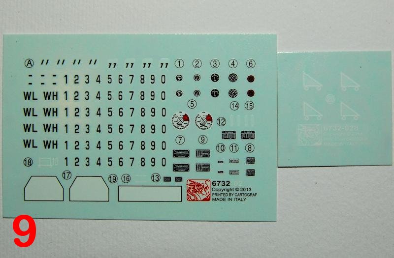
- Two decal sheets: vehicle markings and dashboard (photo 9)
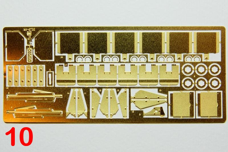
- MA photo-etched sheet of vehicle parts (photo 10)
- Sheet of self-adhesive windscreen painting masks
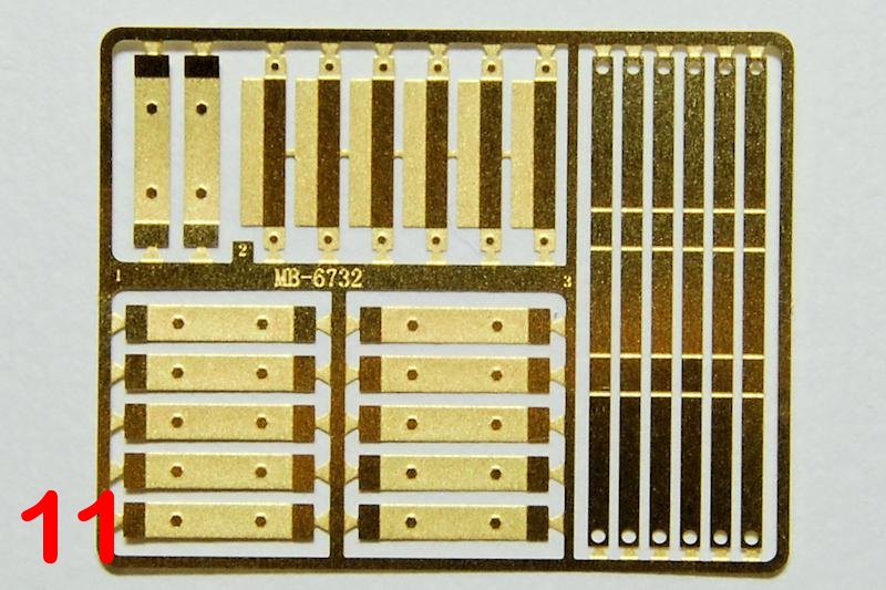
- MB photo-etched sheet of ammunition box mounting brackets (from Dragon 6719) (photo 11)
Review
To summarise, from what I can make out, this Ausf.A replaces the discontinued Cyber Hobby Ausf.A, but on top of that kit, as well as the gun, it also contains the later pattern reinforced road wheels plus the five part road treaded tyres as per various latter Sd.Kfz.250 kits, plus the ammo boxes and the folded canvas top. So quite a number of parts in the box for a relatively small vehicle
As expected everything in the big box is separately bagged and the brass and decals are double packed. The vehicle parts are all very crisply moulded and with minimal mould lines; the gun sprue has a slightly different appearance, just a little less well defined and with somewhat heavier mould lines.
The Half-Track Build
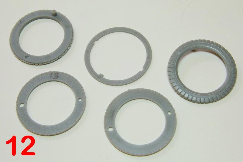
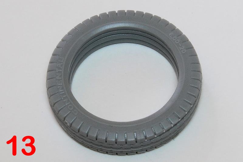
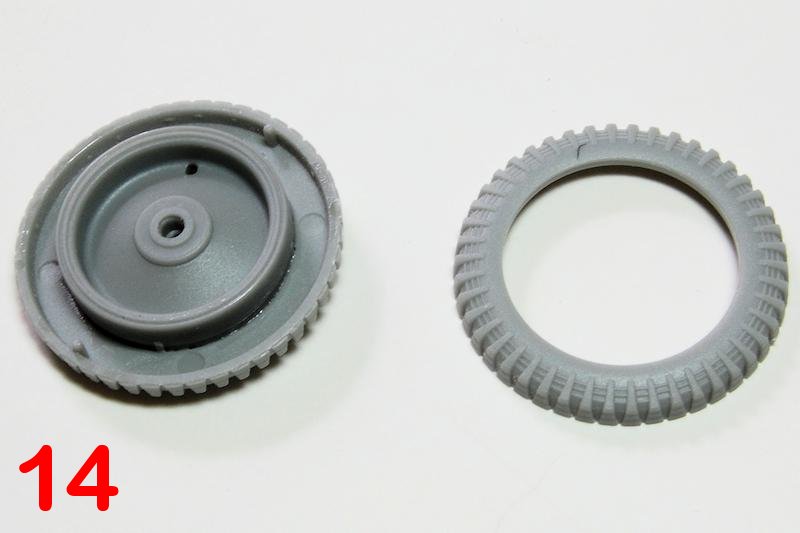
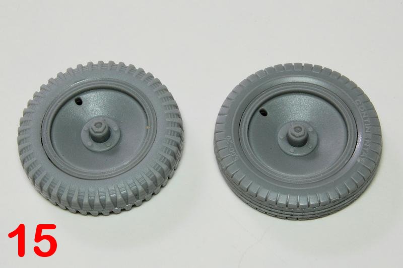
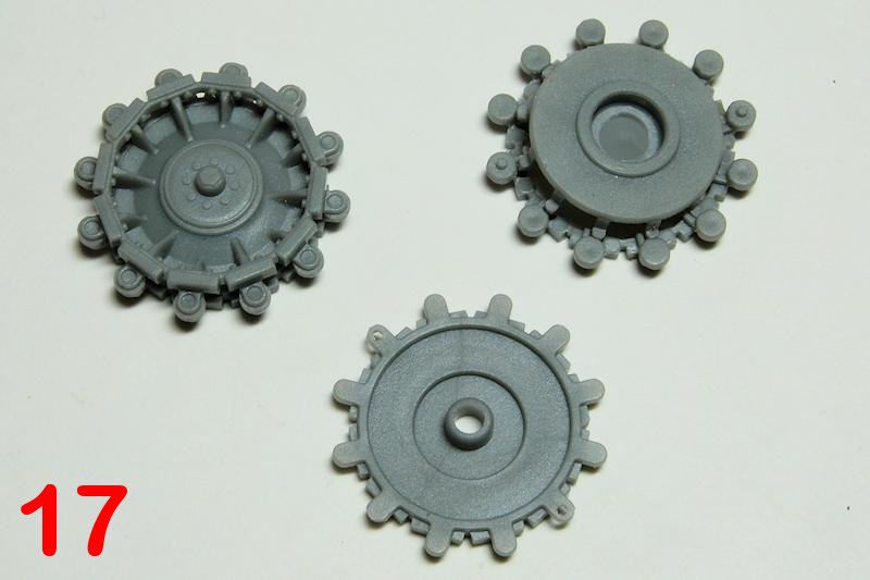
Kicking off with the wheels comes the first option: chunky tyres or road tread tyres? I built one of each and found that the wheel disks themselves, B26 or G6, are interchangeable with both tyre types, G6 being slightly sharper. The five part tyres require clamping while the layers set (photos 1215). The sprockets (photos 16, 17) make up easily enough but these have had criticism for being too narrow, and in my view there are other issues that I will come to. Note that the road wheels are the later, reinforced type wheels, not the plainer faced early type.
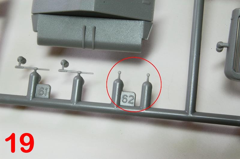
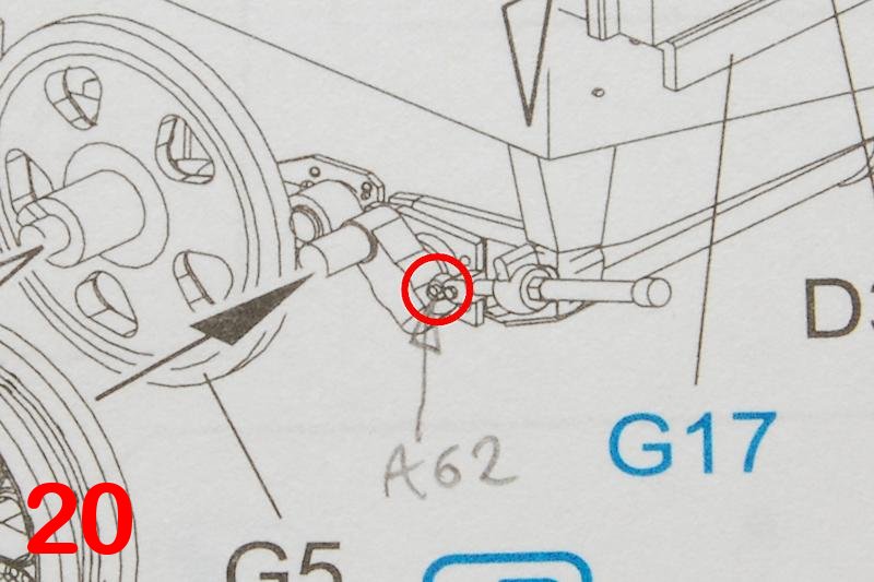
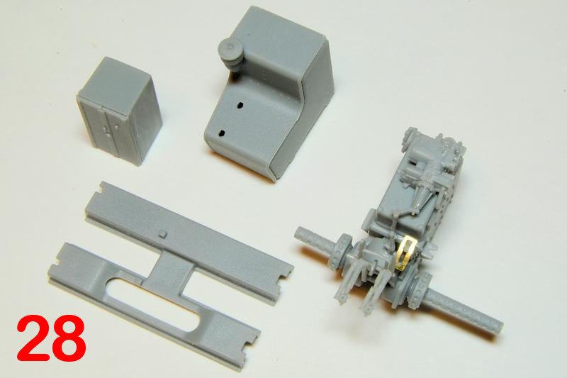
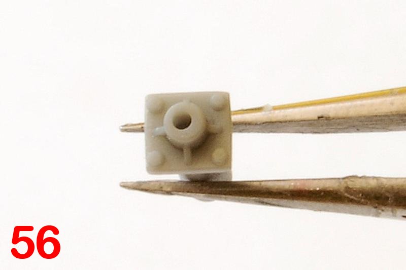
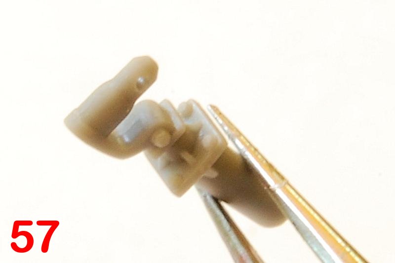
The kit contains two hull rear plates, and its D24 that makes it an Ausf A, not A60. (As an aside, the Ausf.B kit also includes both parts but shows them as two options, and it lacks other hull reinforcement features that would make it accurate as an Ausf.B.) This is the point, step 2, where the instructions start to be a little frustrating; big arrows indicating vague locations for brackets and towing parts, and I scanned forwards for a view of the completed assembly. It is also here that I encounter the oddest component: A62 (photo 19) appears to be a single nut or bolt, intended to attach, I think, to A41/42 (photo 20); why it isnt just moulded in place I cannot understand. I tried to clean it up and glue it in place, but somehow it just disappeared while I was looking at it
Note too that some of the small parts being attached to the hull at this and other stages would be better left until later.
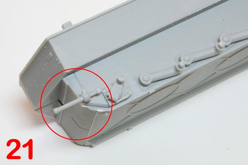
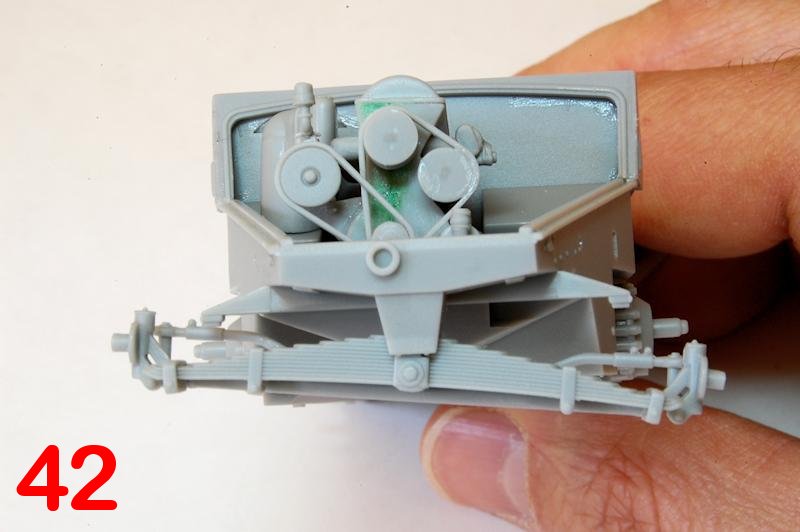
The full length torsion bars slot into the hull accurately and tightly, I didnt even use glue, and it would, I think, be possible to set them at different angles in order to represent travel on rough terrain. I did reflect that it is a shame in a way that the idler and sprocket were not similarly able to be just slotted in, as that might have allowed the entire tracked unit to be fully assembled and then slid off the hull for the purpose of painting; instead you must plan how you are going to tackle the construction and painting of these units. The idler mount was lightly cemented in place with a view to adjusting it later when fitting the tracks (photo 21).
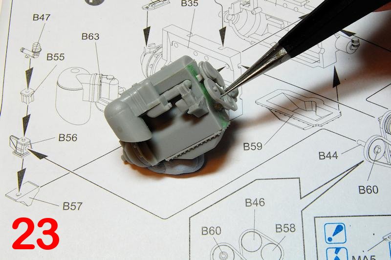
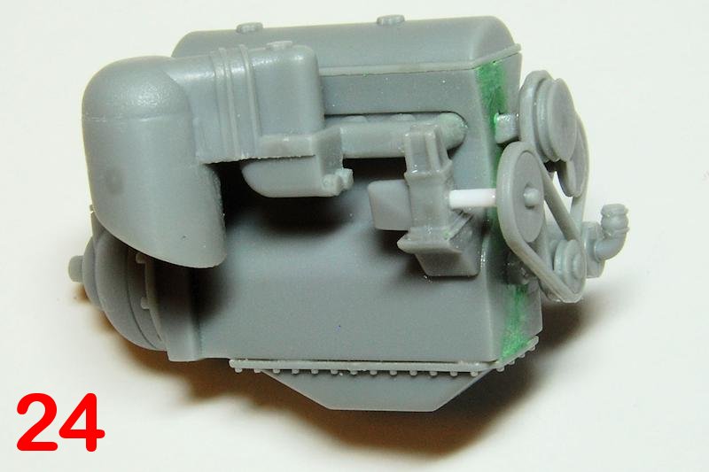
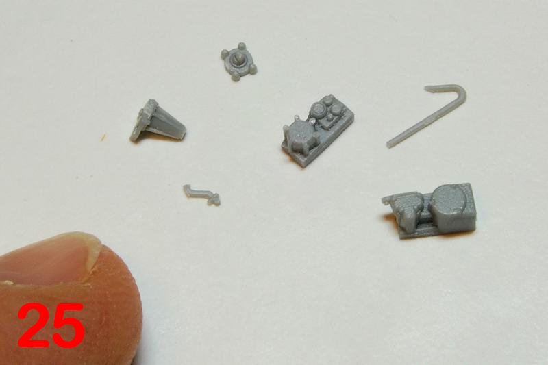
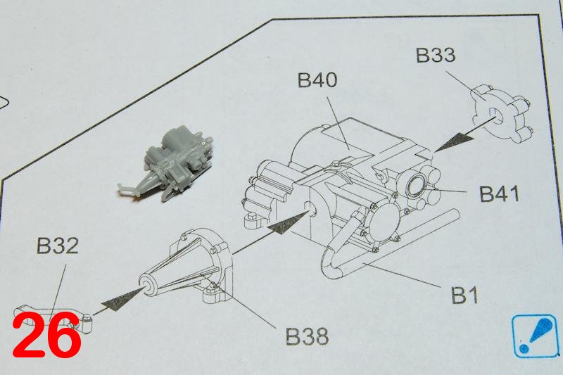
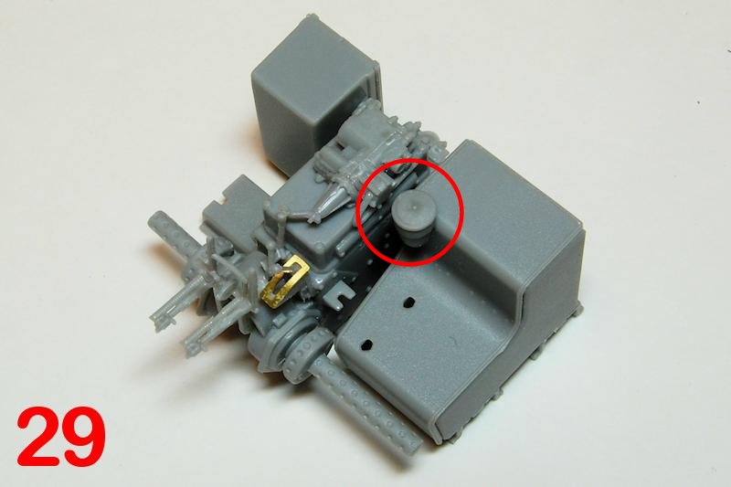
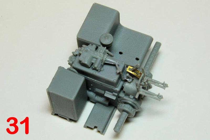
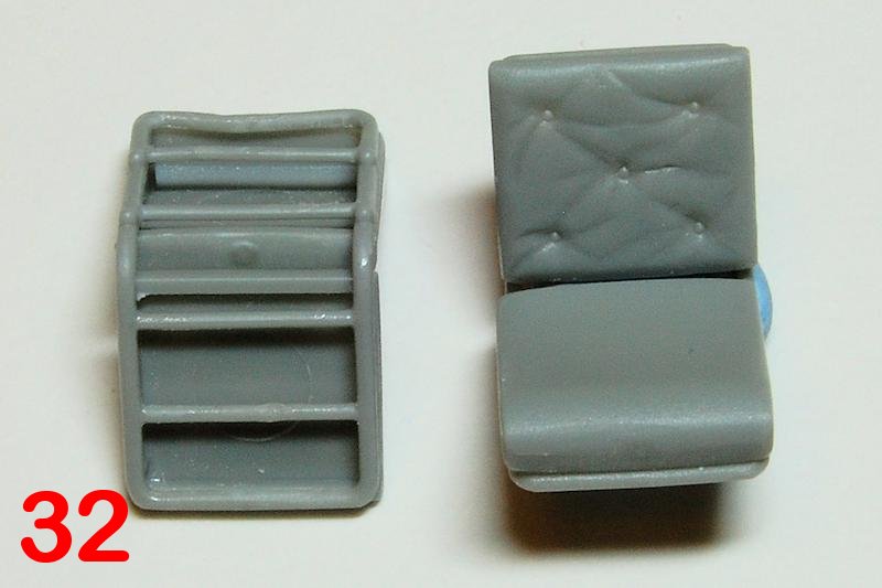
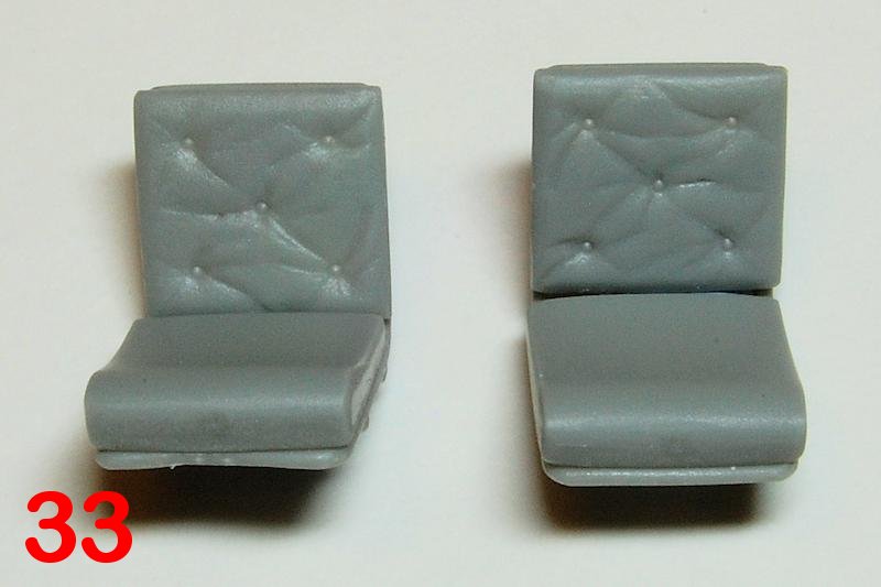
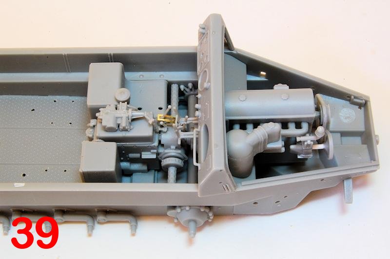
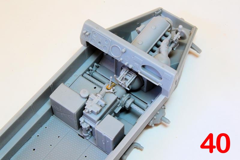
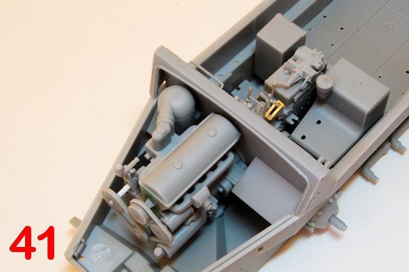
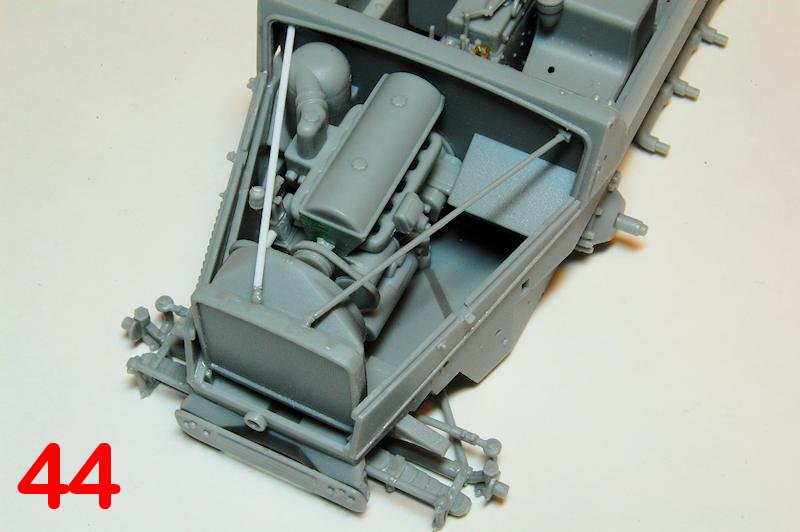
The engine goes together quickly (photos 23, 24) though the main vertical joint was poor, and the detailing is very basic in comparison to the rest of the kit. You could use it a basis for a fair bit of modification and detailing if you wanted it on display or you could just ignore it and cement the hood down. In some contrast is the automatic transmission and gear levers which are exposed in the drivers cab: a pretty fiddly construction that is much smaller than the instructions make it look, and to be frank, the detailing on the plastic doesnt quite match up to the CAD drawing! (Photos 25-28) The fit of these parts is OK, if occasionally unclear, as with B39 for example, which needs to sit right on the edge of B11 (photos 29-31) to allow the passenger seat enough room, and some of the pieces need careful handling if they are not to be damaged during clean up. The seats are best made but not installed until after painting (photos 32, 33).
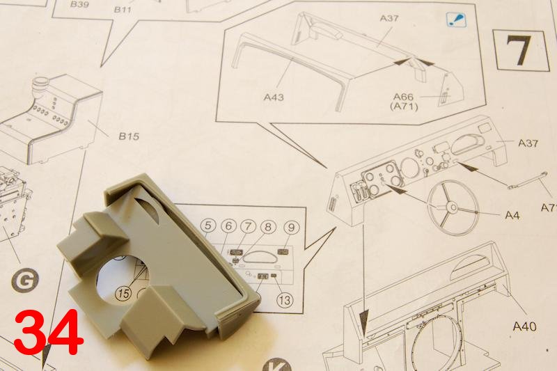
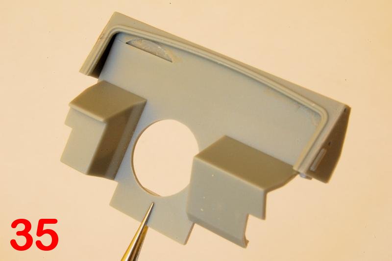
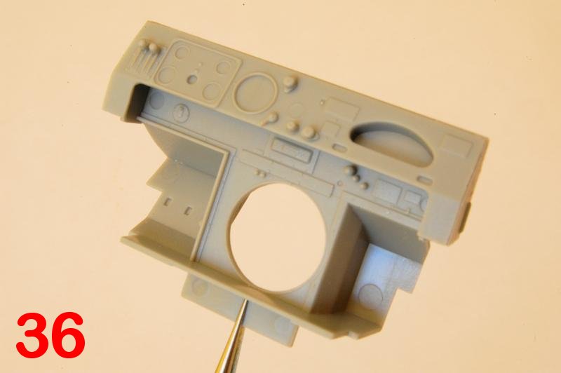
For the dashboard, the instructions, although telling you to take care (a blue !), imply that A37 subassembly can be completed first and then attached to the bulkhead A40 (photo 34); instead you need to build the assembly around the bulkhead, otherwise the cut outs for the cubby hole wont engage. (Photos 35, 36) Incidentally, theres more fantasy detailing in the instruction drawings of the dash that doesnt exist on the plastic parts.
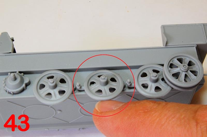
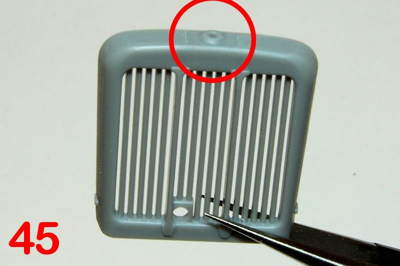
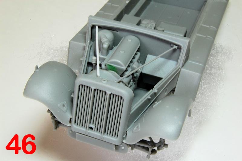
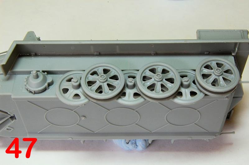
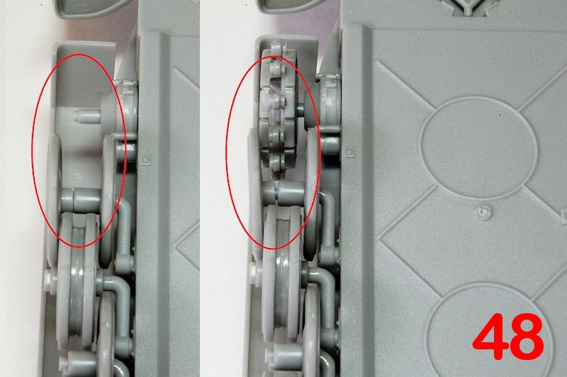
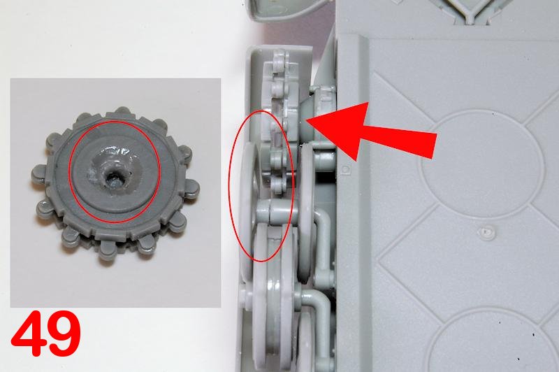
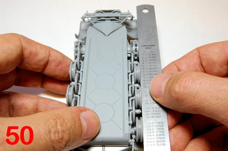
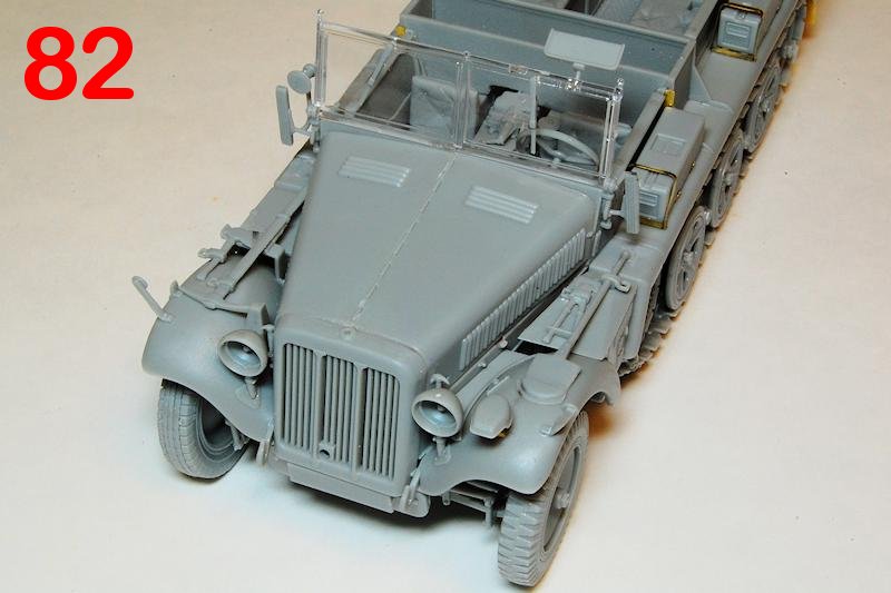
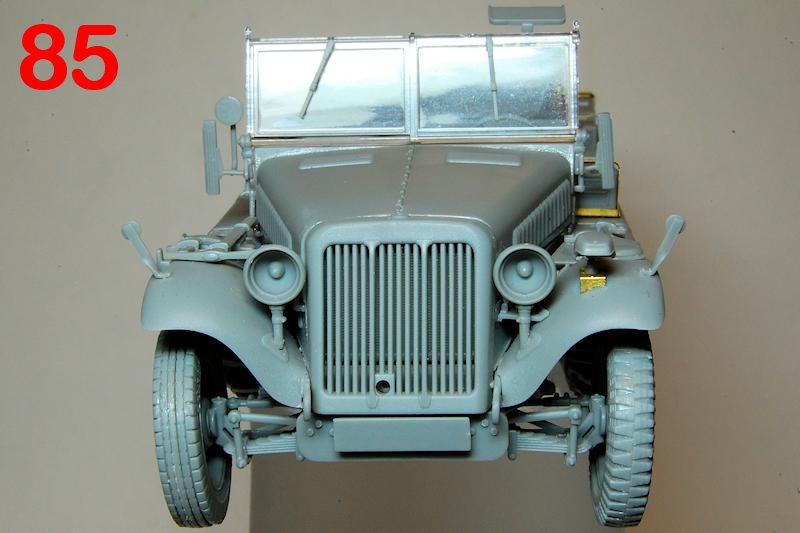
The wheels should be easy though I dont see why, when the torsion bars fit so exactly, that the wheels sit on the bars in some wobbly vague manner, when you want them to be perfectly straight (photo 43). So I left the first row to set while I tackled the radiator; note the front grille has an odd bit of moulding around the filler cap that probably needs to be smoothed off (photo 45). It might also be best to attach the grille at the same time as the bonnet panels to ensure that it all lines up properly. Back to the wheels, the next row went on, (photo 47) then I noticed an alignment problem between the front outer wheel and the sprocket; simply cutting off that last piece of the drive shaft wasnt enough to bring the sprocket within the two front wheels (photo 48). I had to remove much of the centre of the inner face of the sprocket so that it would sit exactly between the front wheels (photo 49). Again the wobbly fit of the wheels means some careful alignment and checking is needed while the cement sets (photo 50).
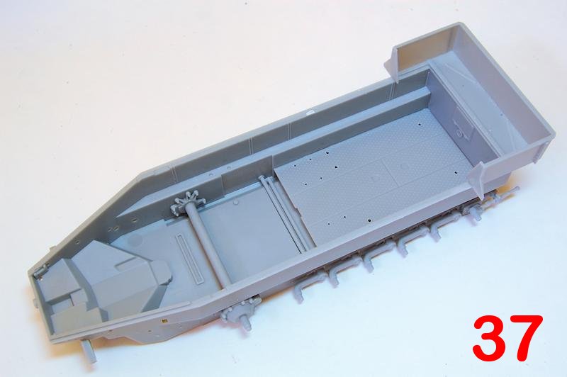
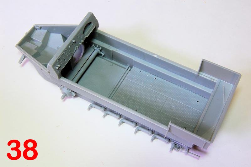
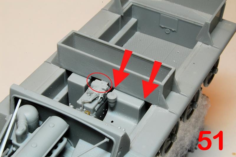
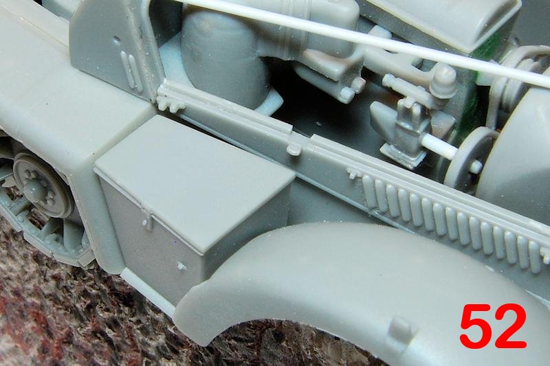
A lot happens in sections 8 and 9, so it pays to be attentive so as not to miss parts out or do anything in the wrong order, though the sequence is not at all clear. The stowage box that divides the front seats from the rear is an easy assembly, but fitting it in the hull proved surprisingly difficult: theres a cut-out (ringed, photo 51) to allow the transmission unit to sit underneath, but its not big enough and needs to be enlarged so that the two ends of the box contact the hull sides. Theres also two tiny cut outs that fit with the ridges around the edges of the structure that the drivers seat mounts on and which had to be cajoled to line up while the cement set (arrowed, photo 51).
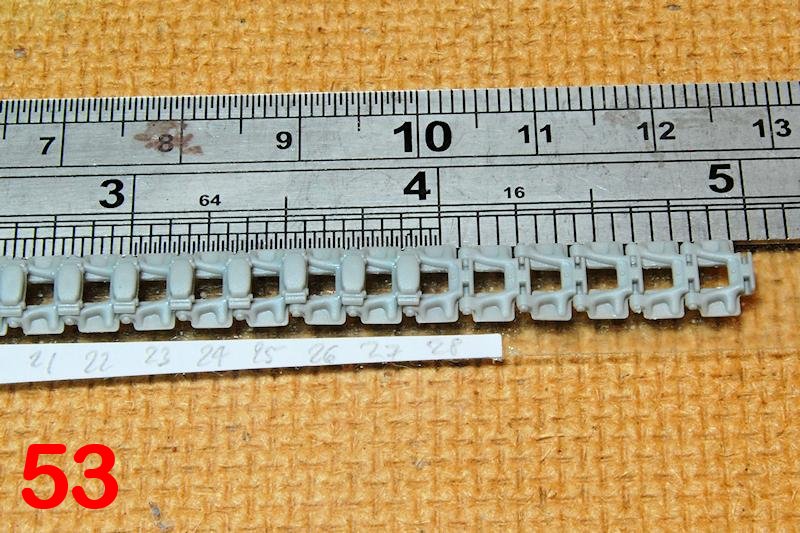
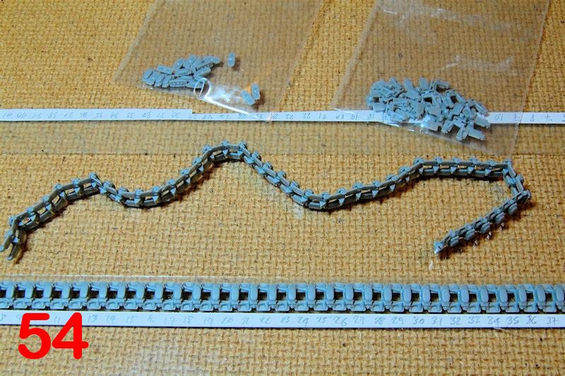
Though the tracks are called in near the end I thought it better to get them in place before the final details went on, so started building them. 42 links per side didnt take too long, with only minimal clean-up of parts, keeping them aligned on double sided sticky tape (photo 53). The pads fit on the links with some latitude in how they assemble, so care is needed to fix them in the right place, with sufficient glue to hold them, but little enough to allow the links to articulate (photo 54).
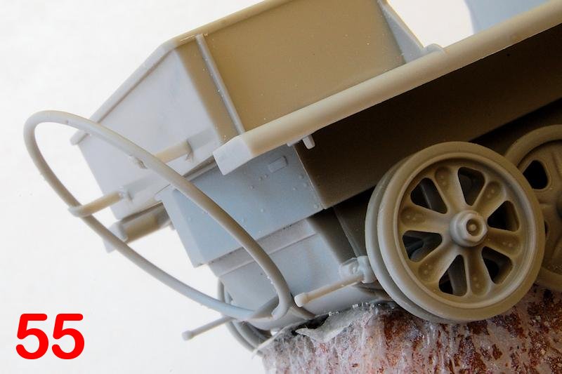
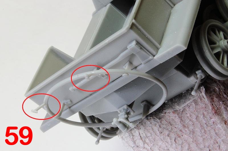
The cable carrying hoop (K-roll) on the back (photo 55) is best left until near the end of the build, most especially the stays (photo 59) which poke straight out and are the rear most part they
will fall off later if you glue them on when told to! Some etched brass rings are intended to be glued to the hoop, but their diameter is bigger than the hoop section, and it would be easier and look better to carefully cement thin styrene rod in place; again, I dont understand the kit designers decision making process here: the etched detail provides more work and a worse look than moulded detail would, and I just ignored them for now.
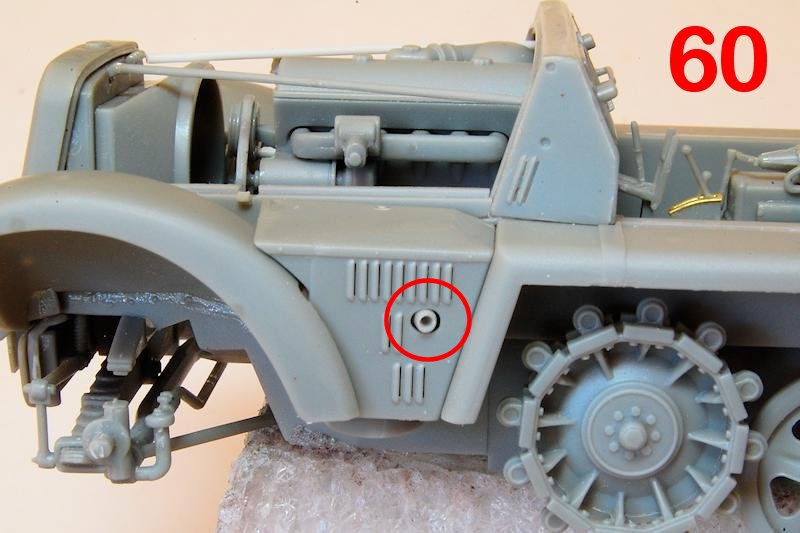
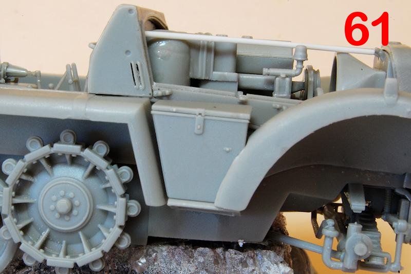
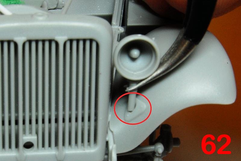
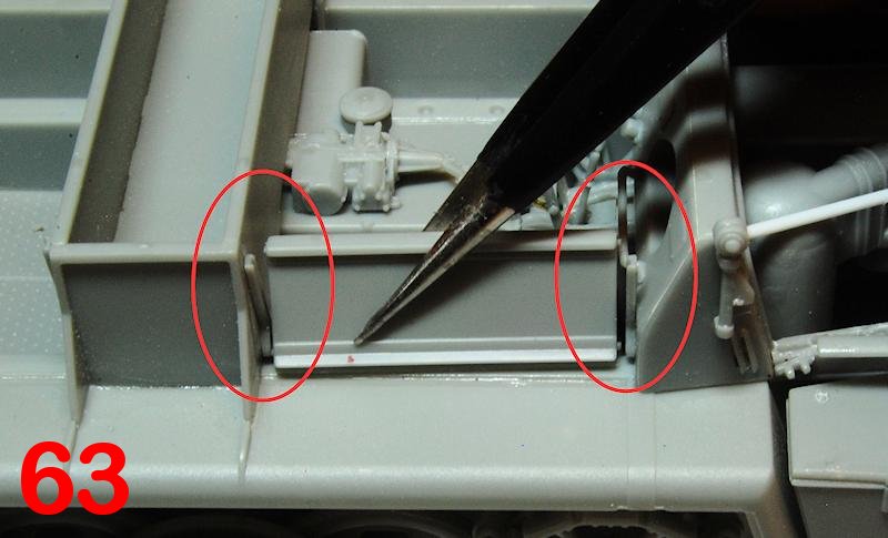
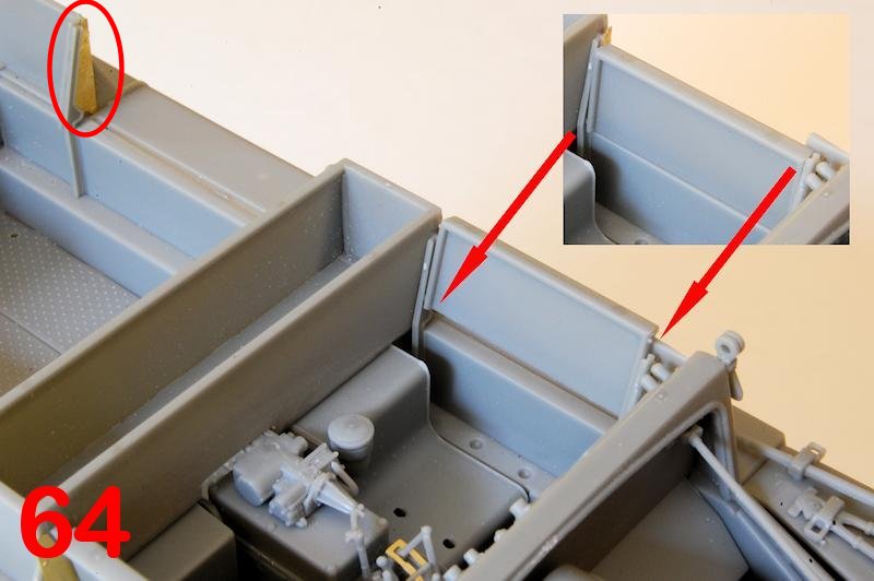
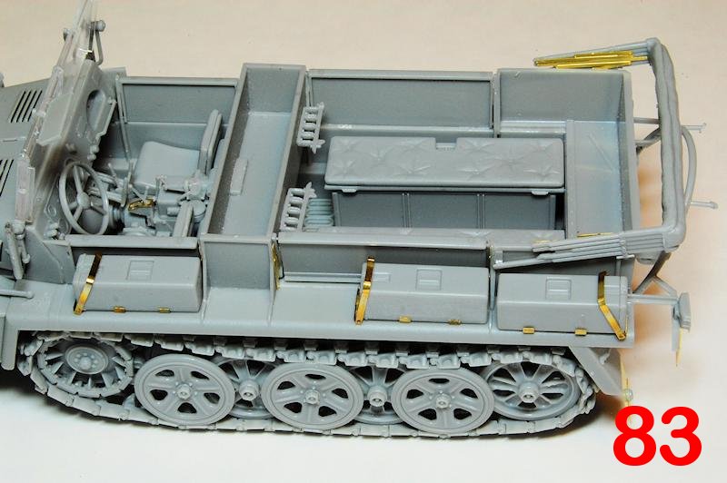
The exhaust cover (photo 60) and the opposite locker (61) fit well, though the exhaust pipe being split in two is a disappointing design, primitive compared to many of the details in this kit (ringed, photo 60). Another example of vague fit occurs with the headlamps, themselves nicely moulded, but the stems barely fit in the shallow indentation on the bodywork (photo 62). The upper body side panels are designed to slide up and down in runners, with small pips engaging with slots, just like the real thing; a nice idea, but I found the right front panel didnt quite fit (photo 63) if the runner was positioned against the dash it needs to move slightly back from that position on both sides; on the left this will also prevent a clash with the levers on the end of the dashboard. This error was caused by the markers for the runners being in slightly the wrong place. It looked too as if in the stowed, i.e. down, position, there may not be room to fit the front seats, so I cemented all in the up position. The etched metal plates that fit either side of the panels are a fiddly detail that might have equally well been moulded in place (ringed, photo 64).
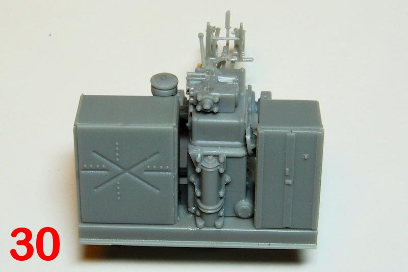
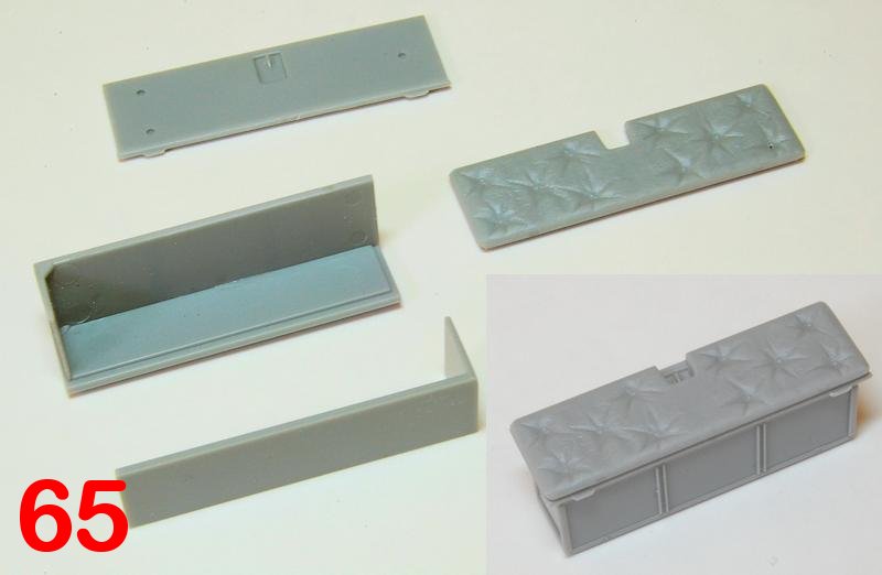
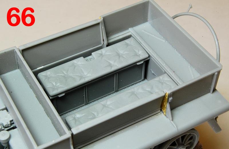
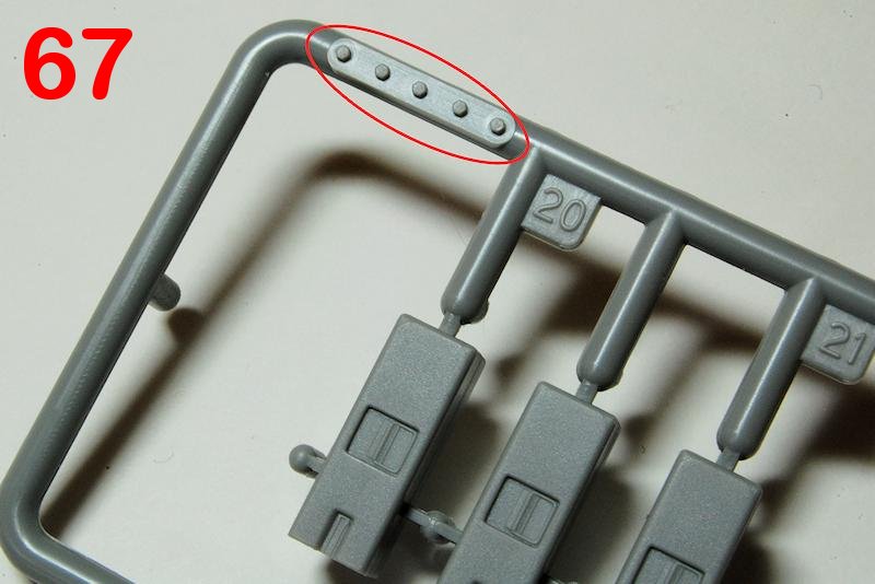
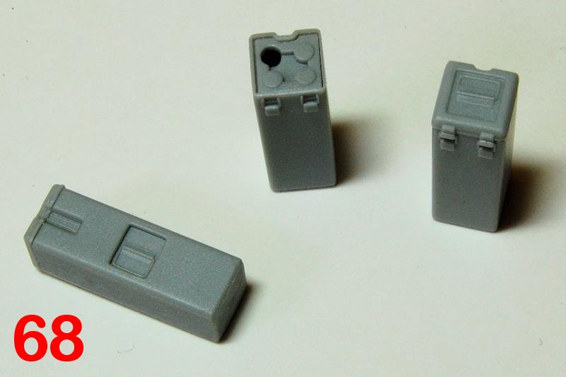
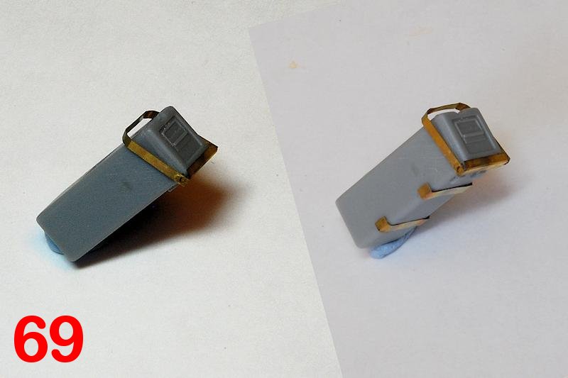
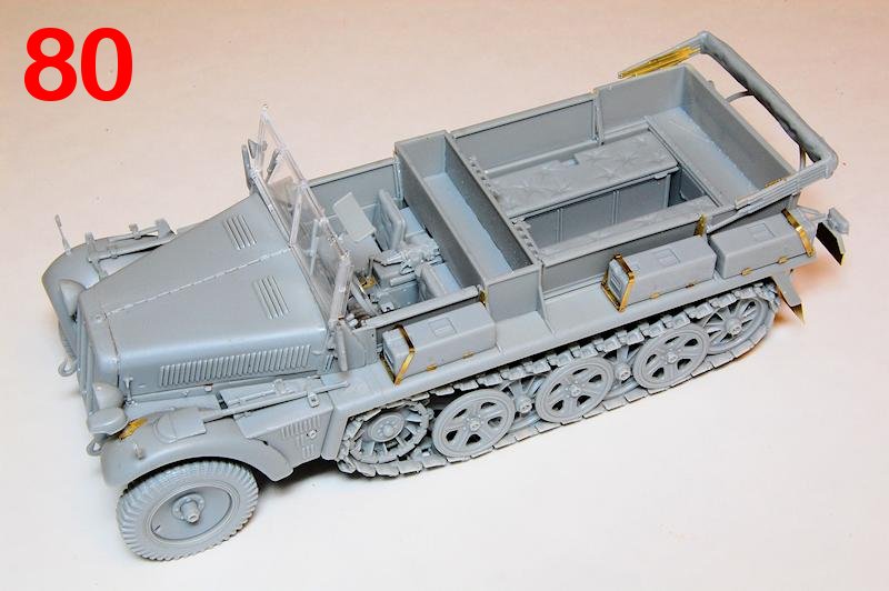
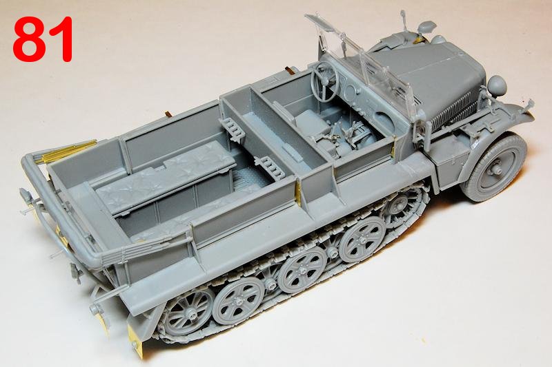
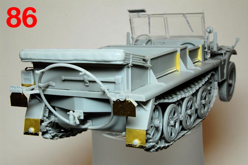
The rear locker / seat units assemble perfectly and locate to fill up most of the rear space (photo 66). The six 5cm ammunition cases (the sprue has 5 bolts moulded in place, not sure what for, photo 67) can be modelled with all lids closed or with two open to display three out of four stowed shells (photo 68). The reference photo and line drawing in the Panzer Tracts book, and the Volstad box top painting all show the boxes as being reinforced with X shaped pressings, something that the kit items lack I dont know if there is evidence that the plain boxes are authentic, but modifying them to include the Xs wouldnt be easy. They mount to the body on pairs of etched strips (photo 69), but I dont think it works well, as the box hinges are thicker than the very thin strips, so that the boxes sit at a slight tilt and it doesnt really look like the real thing (see final photos); reworking these in polystyrene strip may well be a better option.
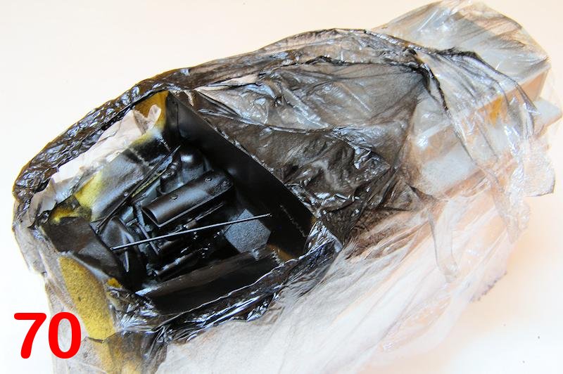
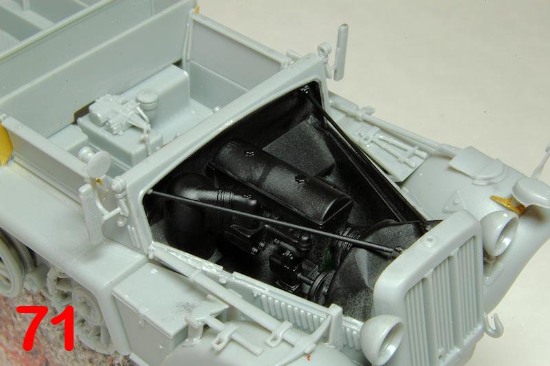
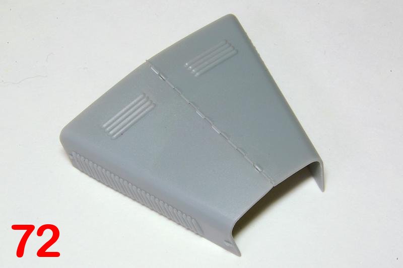
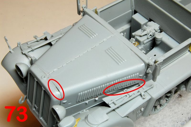
Before fixing the engine covers I wanted to ensure that thered be no grey plastic visible through the beautifully moulded open side slats, so everything else was masked off and the whole engine compartment was sprayed black (photos 70, 71). As the engine covers are hinged down the centre, this is the join to ensure has a perfect fit so was glued first (photo 72), while the fit of the covers on to the vehicle was tight with some force being needed to cement it in place, and though there are some gaps, as indicated (photo 73), I think they can be tolerated as on the real thing its just thin sheet steel that probably had some flexibility. Here the tools, width indicators and Notek lamp are all in place; careful study of reference images and plenty of trial fitting was needed to work out the exact positions, as there are no location markers, though once in place, the fit was good.
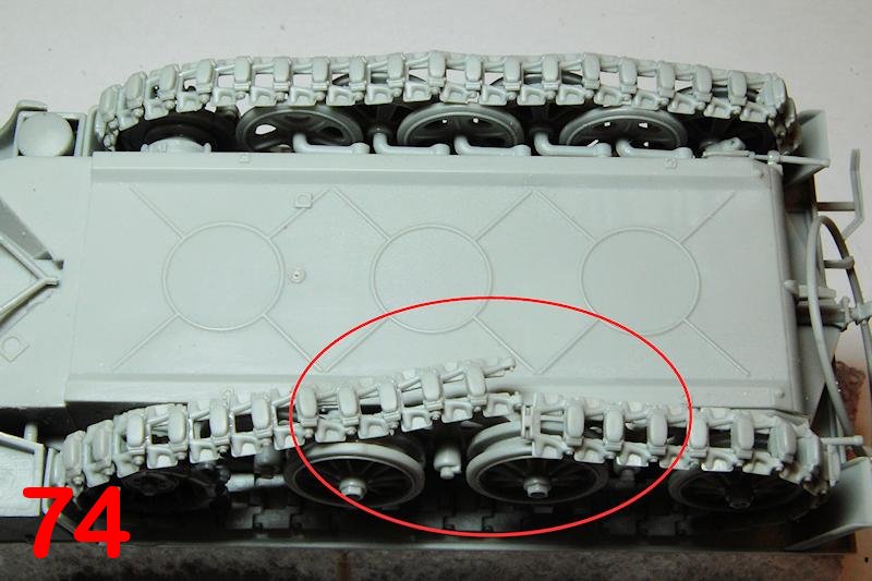
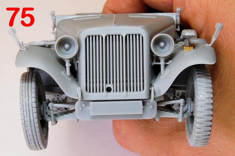
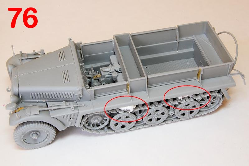
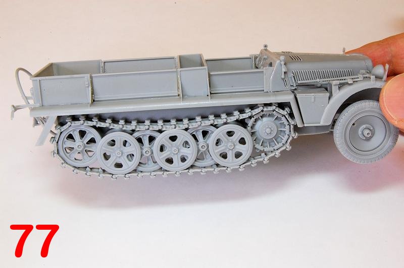
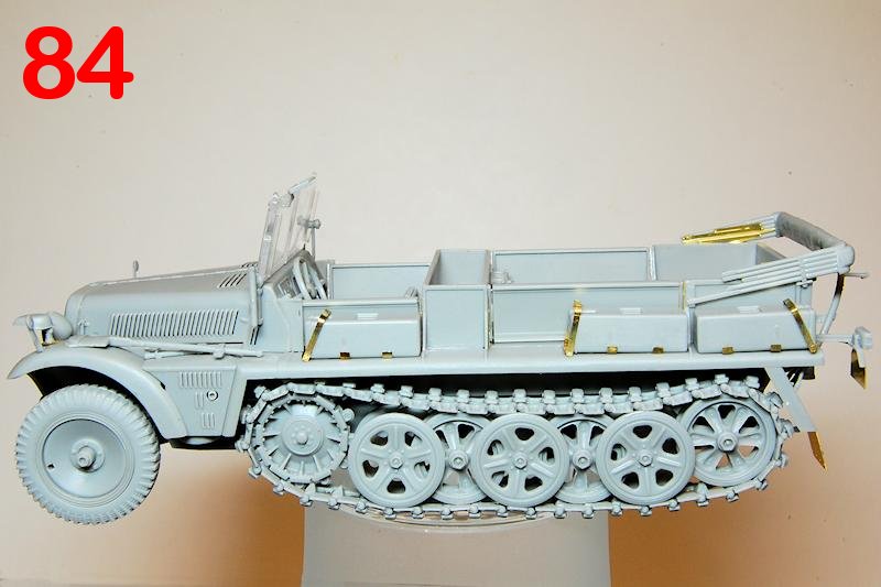
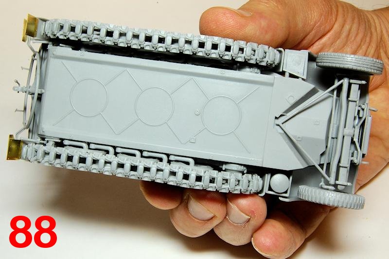
The tracks can be fitted with the track guards in place, provided the links do articulate. Once the final link (photo 74) was joined, I slightly rotated the idler mounting arm (only lightly glued earlier) to add more tension to the tracks. While that set, the front wheels went on at the slightly raked-in angle (photo 75) then back to the tracks, some balls of tissue forced the upper run to sag on to the wheels (photo 76). The completed tracks look good (photo 77), but theres clearly something not right about the sprocket: theres a visible gap between the track plates and the flat sprocket faces, while on the real thing this is perfectly flush, and there is too much track visible at the edges, i.e. the sprocket must be too narrow, yet it still has to fit within the front road wheel, which, with the rest of the outer wheels, should probably sit further on to the edge of the track; the tracks also have teeth that seem to be slightly the wrong shape.
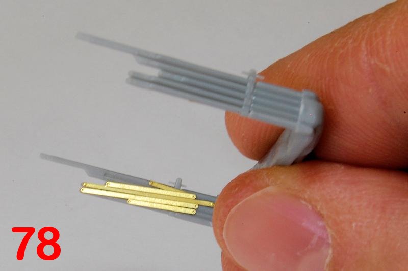
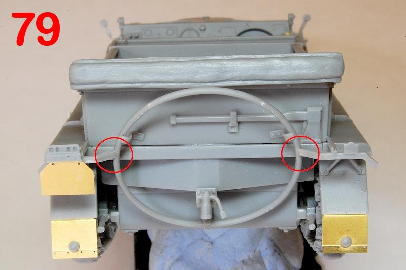
Nearing the end, but theres still a fair number of small details to be added. Etched metal provides detail for the folded struts of the hood (photo 78); this and the overall fit is good, though the moulded folded hood, as usual, looks like a lump of plastic (photo 79), but at least provides a basis that could be worked on. The rear mudguards fit well with the metal flaps needing to be angled to hang more or less vertically. The inner ends of the brackets for the licence plates and rear lamps needed trimming to join up to the cable hoop (ringed, photo 79). Finally, the windscreen, with its delicately mounted rear view mirror and wipers, the wing mirror and search lamp, and last of all those rods that poke out of the back of the cable roll, can all be attached. After this point, extreme care needs to be taken with handling!
Conclusion
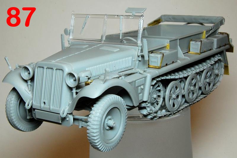
This is a detailed looking model, particularly with the open mouldings of the radiator grille, engine and exhaust cover vents adding to the finely rendered appearance. The driving compartment also looks authentic with the complex gear shift mechanism contrasting nicely with the texture of the buttoned leather seat pads. Although you dont get rifles in this kit, the folded hood and six ammo boxes makes it somewhat less sparse looking than the Ausf.B kit. With the addition of the gun in tow, all youll need is a crew.
The moulding quality of the halftrack is first rate, with just the barest of clean up necessary, and though the precision of fit of major parts is generally very good, there are some areas of seemingly poor design. While there is a logic to designing and breaking down kit parts to be as much as possible like the real parts, sometimes reduction in scale means that the end result is either unnecessarily complex or inconvenient (e.g. the track / wheel assembly) or just doesnt quite fit correctly (e.g. the folding side panels). I am confounded too by the fact that it is possible to design and mould the engine grille so precisely, while the wheels and lamps flop around so vaguely on their mounts surely they dont have to be like that? The engine, as mentioned in other reviews of related kits, isnt up to the standard of the rest of the kit, being not only inaccurate but insufficiently detailed to warrant display. There are also the various sprocket and track issues described above.
Id say that it is absolutely necessary to have some decent reference material to hand while building this. The instructions painfully lack as-built drawings that show precise locations of so many of the parts; the exploded drawings coupled with few moulded in location points mean that you really do need to work out for yourself exactly where many pieces fit. At some points during steps 8 12, things get a little crazy, with so many parts sitting on so many arrows, and concentration is required to ensure nothing is missed. You will also need to consider carefully the order of assembly, partly depending on how you prefer to tackle painting. The interior and the tracks make it complex to paint in one piece; obviously I have fully assembled it for the purpose of the review, though deliberately kept glue very light so that I can potentially dismantle some of it. Painting subassemblies, then assembling, then retouching, is probably the way to go.
References
Thomas Jentz and Hilary Doyle Panzer Tracts No.22-1 Leichter Zugkraftwagen 1t (Sd.Kfz.10) Ausf.A und B and Variants (Panzer Tracts, 2009)
Demag-D7 Sd.Kfz.10 Walk Around on Prime Portal
Related reviews
Sd.Kfz.10/5 with armored cab
SdKfz 10/4 1939 Production
Sd.Kfz.10 Ausf.B 1942 Production


Comments